


Setpoints and Alarms in Control Systems: Principles, Accuracy, and Best Practices
- 〡
- 〡 by WUPAMBO
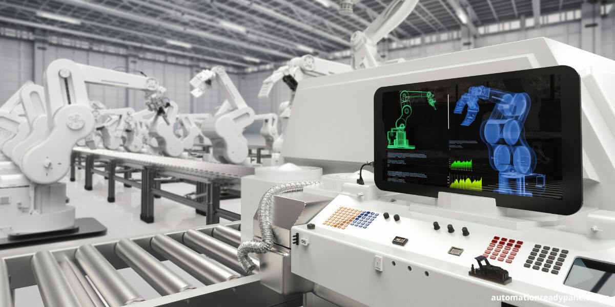
In industrial automation and process control systems, setpoints and alarms play a crucial role in maintaining operational safety and efficiency. These parameters define when instruments trigger corrective actions or warnings to prevent process deviations. Understanding how to configure setpoints with proper accuracy and margin is essential for reliable control system performance.
Understanding Setpoints and Alarms in Industrial Control
Setpoints define the specific values at which an instrument or control system initiates a response—such as activating a shutdown, triggering an alarm, or preventing unsafe operation. In PLC- and DCS-based control systems, setpoints are applied to key process variables such as pressure, temperature, flow, and level.
For example, pressure transmitters on a main steam line monitor system integrity. If the pressure drops below a defined setpoint, the control system automatically initiates corrective actions, such as closing valves or activating safety interlocks. Proper configuration ensures both equipment protection and personnel safety.
Importance of Setpoint Margin and Accuracy
The margin between a setpoint and a technical specification limit is vital. This margin accounts for instrument inaccuracies, sensor drift, vibration, and environmental factors. When margins are too small—or when setpoints equal the maximum allowable limit—there is no tolerance for measurement errors, increasing the risk of unsafe operation.
Moreover, improper calibration or poor design can cause the measured parameter to drift outside of safe limits. Ensuring adequate setpoint margins prevents false trips and ensures consistent performance under varying plant conditions.
Author insight: Many process incidents stem not from faulty equipment but from poorly configured setpoints that fail to include sufficient safety margins.
Common Causes of Setpoint Drift and Inaccuracy
Setpoint drift often results from instrument design limitations, mechanical wear, or inadequate calibration methods. Over time, changes in the input-output relationship of sensors cause readings to shift. If calibration intervals are too long, accumulated drift may render the setpoint ineffective.
Environmental conditions also play a major role. Temperature fluctuations, humidity, and vibration can alter sensor accuracy. Using industrial-grade instrumentation with proven long-term stability—from manufacturers like Siemens, Yokogawa, or Honeywell—helps minimize drift effects.
Key Definitions in Control System Calibration
To understand setpoint configuration clearly, it’s important to know these related terms:
-
Instrument Accuracy: The degree to which the measured value matches the true process value.
-
Drift: Gradual change in an instrument’s output over time under constant input.
-
Margin: The buffer between operating and limiting conditions.
-
Range: The measurable span between the minimum and maximum process values.
-
Safety Limit: The boundary condition required to prevent damage or unsafe operation.
-
Span: The numerical difference between the upper and lower measurement limits.
-
Technical Specification Limit: The regulatory or design constraint defining the safe operating boundary.
Designing Safe and Reliable Setpoints
Setpoints in safety-critical systems—such as those protecting pressure vessels, turbines, or reactors—must include allowances for measurement uncertainty and calibration drift. Control engineers should calculate setpoints based on:
-
Instrument accuracy and repeatability
-
Expected environmental conditions
-
Time interval between calibrations
-
System vibration and process stability
All setpoints must fall within the usable portion of the instrument span to maintain reliable readings. Instruments should be calibrated specifically at the setpoint value to ensure accuracy under real operating conditions.
Selecting the Proper Instrument Range
When designing a control system, select an instrument range that comfortably covers the expected process conditions. Avoid using ranges that place the setpoint near the upper or lower end of the scale, as saturation or nonlinearity can distort readings and reduce control accuracy.
Author insight: A well-chosen range not only improves precision but also extends the instrument’s service life by preventing overloading or excessive cycling.
Maintaining Accuracy and Mechanical Integrity
Instruments exposed to harsh industrial environments—such as high vibration, pressure cycling, or temperature extremes—must resist annealing, stress relief, or work hardening. If not properly designed, these physical effects can cause mechanical deformation and compromise accuracy.
Manufacturers typically verify these conditions through design validation and environmental testing, ensuring long-term reliability for industrial applications.
Securing Setpoint Adjustments
Each instrument’s setpoint adjustment mechanism should have a mechanical or administrative locking device. This prevents unintentional changes due to vibration or human error. A secure adjustment system also supports traceability, as any modification must be documented under quality management protocols.
In modern digital instruments, software-based security—such as password protection or electronic audit trails—has replaced physical locks. This approach aligns with best practices in industrial cybersecurity and regulatory compliance.
Documentation and Verification of Setpoint Values
Every setpoint selection should be documented, including the margin assumptions, expected drift rate, and calibration intervals. These records form part of the safety system analysis and ensure compliance with regulatory standards such as IEC 61511 and ISO 13849.
Consistent documentation also allows maintenance teams to track performance trends and identify early signs of sensor degradation.
Application Scenarios in Industrial Automation
Case 1: Steam Pressure Protection System
A pressure transmitter detects a drop below 90% of nominal pressure. The PLC activates a shutdown sequence to isolate the main steam line, preventing equipment damage.
Case 2: Reactor Temperature Control
Temperature setpoints are configured with ±2°C margin to account for thermocouple drift. Automatic calibration ensures precise thermal control during long production runs.
Case 3: Pump Motor Overload Alarm
The DCS monitors motor current against a predefined limit. When current exceeds the setpoint for more than 3 seconds, the system triggers an alarm and reduces motor speed.
Conclusion
Accurate setpoint configuration and alarm management are fundamental to safe, efficient control system operation. Engineers must consider instrument accuracy, environmental influences, and drift rates to establish reliable setpoints. Regular calibration, documentation, and design verification ensure compliance and prevent unplanned shutdowns.
A disciplined approach to setpoint management enhances plant safety, equipment longevity, and operational consistency across modern industrial automation systems.


