Demystifying Signal Isolators: Operating Principles, Architectural Types, and Industrial Applications
- 〡
- 〡 by WUPAMBO
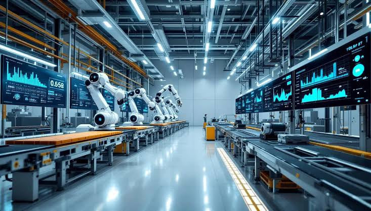
Industrial automation systems rely on pristine analog signal transmission across complex control loops. Instrument technicians and system integrators frequently deploy signal isolators to maintain signal integrity between field sensors and control platforms. Eliminating electrical noise, ground loops, and high-voltage transients protects delicate PLC, DCS, and SCADA input channels from permanent damage.
The Fundamental Purpose of Signal Isolation in Industrial Control
Process plants operate thousands of field instruments across extensive physical layouts. Unintended potential differences between grounded field transmitters and control cabinet analog cards routinely generate ground loop currents. These stray currents introduce measurement errors, distort 4-20 mA current loops, and trigger false process alarms.
Signal isolators establish a physical galvanic barrier between input and output circuits. Galvanic isolation allows the desired process variable signal to pass through safely while completely blocking unwanted DC currents, common-mode voltages, and ground loops. Consequently, isolators preserve high measurement accuracy across sensitive data acquisition networks.
Expert Insight: Modern DIN rail-mounted signal isolators perform double duty in control cabinets. They serve as reliable front-line protection barriers that safeguard expensive DCS I/O cards against unexpected field voltage surges.
Working Principle and Underlying Isolation Technologies
Signal isolators convert incoming electrical signals into a non-electrical medium across an internal isolation barrier before reconstructing the signal on the output side. Manufacturers primarily utilize three core physical principles to achieve galvanic separation:
- Optical Isolation: Uses light-emitting diodes (LEDs) and phototransistors to transmit data via light waves across a physical dielectric gap.
- Transformer (Electromagnetic) Isolation: Employs high-frequency magnetic transformers to couple AC-modulated signals across isolated primary and secondary windings.
- Capacitive Isolation: Uses micro-fine silicon dioxide dielectric barriers to transfer signals via high-speed electrostatic field variations.
Categorizing Signal Isolators: Input Types and Power Architectures
Automation engineers select signal isolators based on specific field sensor outputs and available cabinet power distribution architectures.
Signal Input Categories
- Current and Voltage Isolators: Processes standard industrial analog signals such as 4-20 mA, 0-10 V, or 1-5 V loops to prevent signal cross-talk.
- Millivolt Isolators: Handles low-level voltage signals generated by strain gauges, shunt resistors, and specialized analytical sensors.
- Temperature & Resistance Isolators: Accepts direct inputs from Resistance Temperature Detectors (RTDs like Pt100) or thermocouples, converting them into isolated linear outputs.
Active vs. Passive Power Topologies
- Active Isolators: Requires an independent external power supply (typically 24 VDC). These units actively condition, amplify, and drive signals across long cable runs.
- Passive (Loop-Powered) Isolators: Operates without a dedicated power terminal. The device derives its operating energy directly from the input or output 4-20 mA current loop.
Strategic Comparison: Active vs. Passive Signal Isolators
Evaluating signal isolator architectures requires matching operational constraints against process loop requirements:
| Architectural Metric | Active Signal Isolator | Passive (Loop-Powered) Isolator |
|---|---|---|
| Power Requirement | Dedicated auxiliary supply (24 VDC or 110/230 VAC) | No external auxiliary power required |
| Signal Conditioning | Supports amplification, linear conversion, and filtering | Pass-through transmission without active signal amplification |
| Loop Voltage Drop | Minimal load on the primary input loop | Introduces a voltage drop (typically 1.5 V to 3 V) on the loop |
| Installation Complexity | Requires additional power distribution wiring in cabinets | Simplified two-wire installation reduces cabinet panel footprint |
| System Cost | Higher initial unit cost due to integrated active power circuits | Lower hardware cost and reduced wiring expenditure |
Advantages and Engineering Limitations of Signal Isolators
Integrating galvanic isolators into factory automation architectures provides several operational advantages alongside specific engineering trade-offs.
Key Advantages
- Elimination of Ground Loops: Complete galvanic separation halts unwanted current circulation between disparate ground points.
- Noise and EMI Reduction: Shielding mechanisms prevent electromagnetic interference from disturbing sensitive analog loops.
- Hardware Protection: Isolators shield delicate PLC and DCS I/O cards from severe high-voltage line spikes.
- Simplified Compliance: Standardized DIN rail modules facilitate compliance with international safety and EMC standards.
Operational Limitations
- Signal Latency: Internal conversion stages introduce minor response delays (typically a few milliseconds), which rarely impact thermal or pressure loops.
- Potential Inaccuracies: Low-quality isolators may introduce small conversion errors or temperature drift into precision measurement loops.
Real-World Application Scenario: Heavy Motor Control and Drives in Steel Mills
A major steel manufacturing facility experienced severe 4-20 mA signal fluctuation on speed feedback lines returning from large variable frequency drives (VFDs) to a central PLC.
Implementation Strategy
- Problem Identification: High-power VFDs generated massive electromagnetic interference and ground potential shifts, causing severe PLC reading errors.
- Solution Deployment: Field engineers installed 3-way galvanically isolated active current isolators on every 4-20 mA speed reference loop between the VFDs and the PLC cabinet.
Operational Results
The optical isolation barrier completely eliminated common-mode noise and ground loop currents. Speed feedback values stabilized immediately, allowing the plant to maintain precise roller speed synchronization and prevent material jams.
About the Original Author
Sun Jian is a senior instrumentation engineer and industrial automation specialist with over 15 years of hands-on experience in process control and signal conditioning architectures. He specializes in designing noise-immune field instrumentation networks, safety instrumented system (SIS) interfaces, and robust signal isolation solutions for chemical processing plants, steel manufacturing facilities, and power utilities across Asia and Australia.
- Posted in:
- 4-20mA current loop
- DCS process control
- galvanic isolation
- PLC control systems
- signal isolator