


Advanced PLC Programming for Automatic Industrial Door Systems
- 〡
- 〡 by WUPAMBO
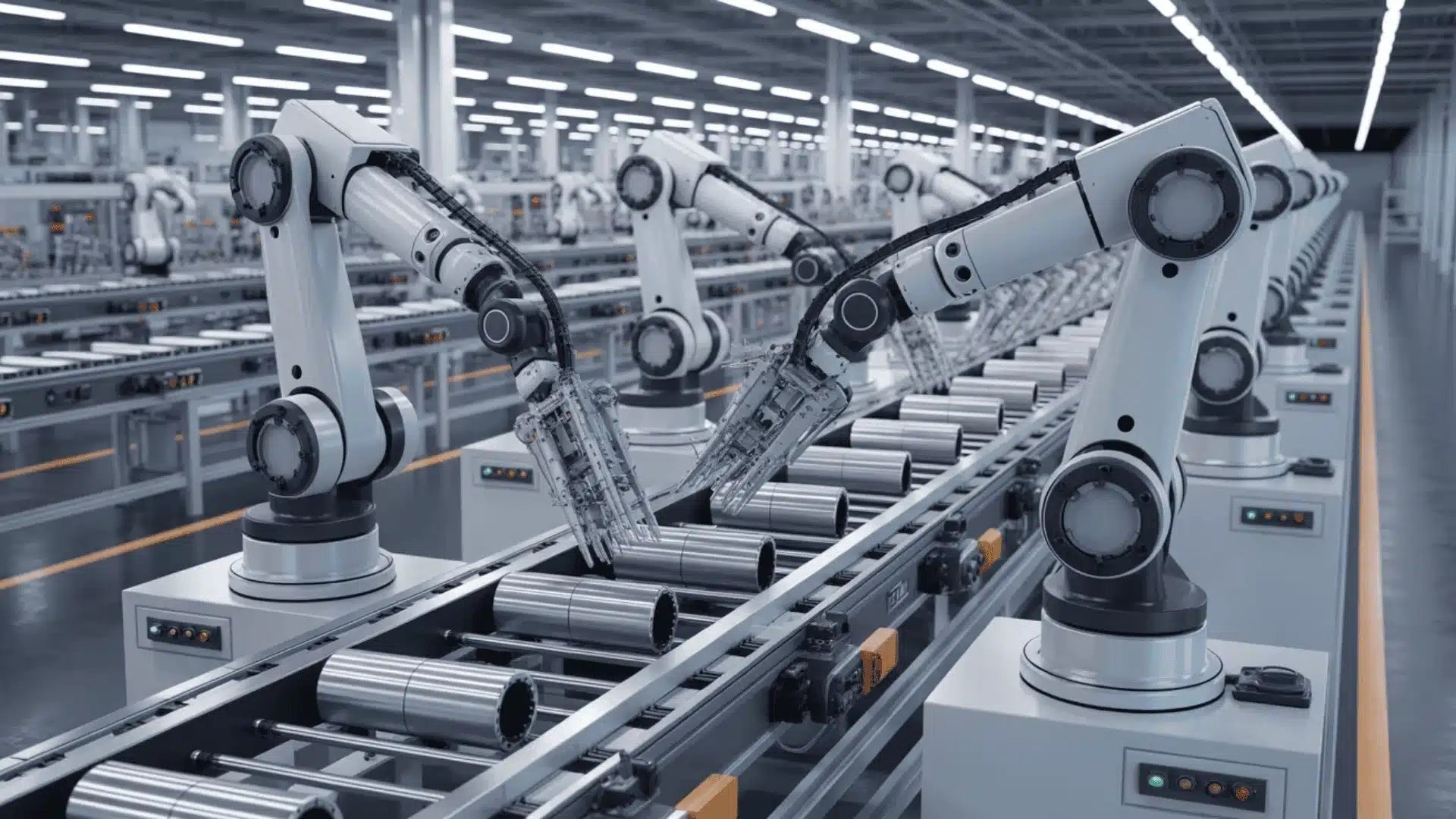
Automatic door control represents a foundational logic sequence in factory automation. While seemingly straightforward, designing a robust control loop requires a deep understanding of sensor integration, interlocking safety mechanisms, and edge-case handling.
This technical guide break downs the implementation of an automated industrial gate control system using Programmable Logic Controllers (PLCs). By examining input/output (I/O) mapping, operational logic, and safety configurations, we will explore how to deliver an efficient and reliable automated solution.
Technical Specifications and I/O Assignment
A structured I/O engineering document forms the backbone of any reliable control system design, whether utilizing a standalone PLC or integrating into a plant-wide Distributed Control System (DCS). For this application, we define the field devices, limit switches, and signaling indicators using a standard addressing schema.
System Components and Addressing Table
| Hardware Device | PLC Address | Signal Type | Functional Description |
| Lower Limit Switch | X0 | Digital Input | Triggers when the door reaches the fully closed position. |
| Upper Limit Switch | X1 | Digital Input | Triggers when the door reaches the fully open position. |
| In-Gate Sensor | X2 | Digital Input | Detects an approaching vehicle at the entrance zone. |
| Out-Gate Sensor | X3 | Digital Input | Detects the vehicle as it clears the exit zone. |
| Door Up Actuator | Y0 | Digital Output | Energizes the motor contactor to raise the door. |
| Door Down Actuator | Y1 | Digital Output | Energizes the motor contactor to lower the door. |
| Status Indicator Light | Y6 | Digital Output | Illuminates when a vehicle occupies the transition zone. |
| Audible Alarm / Buzzer | Y7 | Digital Output | Sounds continuously during any active door movement. |
Sequencing Logic and Core Process Flow
The control architecture manages the physical transition of the gate based on real-time telemetry from the field sensors. Automation professionals must program this sequence to handle dynamic physical variables without system stalling.
Initiating the Opening Sequence
When a vehicle approaches the facility, the photoelectric In-Gate sensor (X2) changes state and transitions to true. Consequently, the PLC CPU processes this input and immediately energizes the Door Up actuator output (Y0). The motor raises the heavy industrial curtain safely. Simultaneously, the audible buzzer (Y7) activates to warn personnel in the immediate vicinity of the moving mechanical structure.
Halting Motion via Limit Triggers
The motor must stop immediately when the door reaches its physical boundaries to prevent mechanical damage or motor burnout. Therefore, the upward movement continues only until the structural frame engages the Upper Limit Switch (X1). Once X1 opens its normally closed contact in the logic, the PLC instantly de-energizes output Y0, bringing the door to a safe, controlled halt.
Managing the Transition Zone
While the vehicle drives through the threshold, it occupies the space between the In-Gate sensor (X2) and the Out-Gate sensor (X3). During this transit phase, the system maintains the status indicator light (Y6) in an active state. This provides clear visual feedback to operators that the control loop recognizes an object within the high-risk perimeter. The PLC holds the door fully open as long as either sensor detects the vehicle presence.
Executing the Closing Sequence
Once the vehicle completely clears the exit perimeter, the Out-Gate sensor (X3) returns to a false state. Because the detection zone is now completely clear, the PLC executes the closing logic by energizing the Door Down actuator (Y1). The gate descends steadily until it trips the Lower Limit Switch (X0). At this precise moment, the PLC drops the Y1 output, securing the facility entrance.
Expert Insights on Industrial Safety and Interlocking
Expert Commentary: Relying solely on basic sequential logic for industrial doors poses severe operational and safety risks. In real-world factory automation, hardware components fail, sensors become misaligned, and vehicles stall mid-transit.
To achieve compliance with global industrial safety standards, such as ISO 13849-1, engineers must integrate robust safety interlocks directly into the PLC ladder logic:
-
Electrical and Software Interlocking: Never rely purely on software to prevent simultaneous activation of outputs. You must cross-interlock the Door Up (Y0) and Door Down (Y1) outputs using both normally closed (NC) contacts in the ladder logic and physical, hardware-wired auxiliary contacts on the motor contactors.
-
Fail-Safe Limit Configurations: Wire the Upper (X1) and Lower (X0) limit switches as Normally Closed (NC) circuits. If a field wire breaks or a switch loses power, the circuit opens naturally. As a result, the PLC interprets this as a limit hit and stops the motor, preventing catastrophic structural over-travel.
-
Anti-Crush Protection: Integrate a safety edge or light curtain alongside the standard inputs. If an object breaks the safety beam during the downward cycle, the PLC must instantly drop Y1 and reverse the motor to Y0 to avoid injury or equipment damage.
Industrial Application Scenarios
Automated Logistics Hubs
In high-throughput distribution centers, this PLC logic automates the entry points for freight trucks. Integrating this sequence with RFID or license plate recognition systems allows seamless transitions without requiring drivers to exit the cabin, maintaining facility climate control and security.
Hazardous Chemical Processing Areas
In heavy industrial plants using a centralized DCS, these automated doors isolate specific processing zones. The PLC controls the local fast-acting curtain doors while communicating status bytes to the overarching DCS, ensuring automated isolation in the event of a hazardous gas leak or thermal runaway.
About the Author: Zhang Junjie
Zhang Junjie is a senior industrial automation engineer with over 15 years of hands-on experience designing, programming, and commissioning complex control systems. He specializes in Siemens S7-1500/PCS7, Rockwell Automation ControlLogix, and various SCADA architectures. Throughout his career, Junjie has successfully delivered robust automation solutions across the manufacturing, oil and gas, and power generation sectors throughout the Asia-Pacific region.


