










Product Details
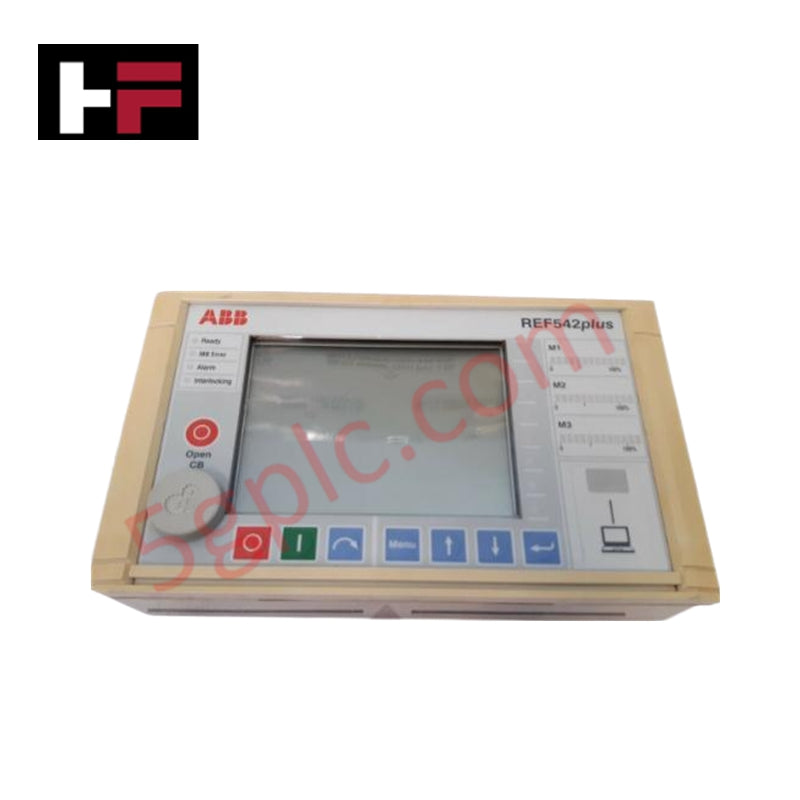
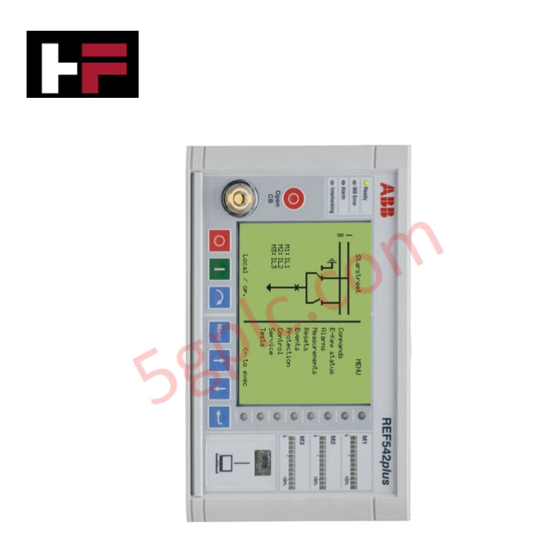
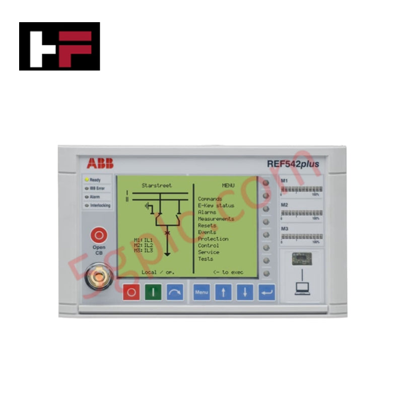
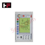
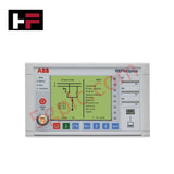
Configured for integrated protection, control, measurement, and communication tasks in medium-voltage switchgear networks, the ABB REF542plus 2RCA029395 (REF542plus Compact Digital Feeder Terminal) provides direct physical/electrical execution. The hardware system samples analog current inputs, computes algorithmic relay thresholds, updates multi-protocol frame registers, and drives mechanical trip coils through localized binary contact channels.
Hardware Specifications
| Parameter | Specification |
|---|---|
| Model | REF542plus 2RCA029395 |
| Brand | ABB |
| Origin | Switzerland |
| Weight | Standard switchgear-mount baseline unit weight |
| Dimensions | Panel-mounted compact format with integrated front HMI |
| Rated Voltage | 100-240 VAC |
| Frequency | 50/60 Hz |
| Current Inputs | 1 A or 5 A (Software selectable/hardware mapped configuration) |
| Operating Temp | -25 to +70 deg C |
| Power Consumption | System bus / auxiliary power network specified |
| Protection Class | IP54 (Front panel face), IP20 (Rear enclosure terminal section) |
| Communication Protocols | IEC 60870-5-103, Modbus RTU, DNP3.0 |
Profinet / EtherNet/IP Deterministic Networks and I/O Density Scaling
The execution rate of the internal logic engine inside the ABB REF542plus 2RCA029395 interfaces strictly with native internal bus lines. When integrating substation process values into upper-level Profinet or EtherNet/IP deterministic networks via protocol translation cards, the unit streams measurement variables without increasing signal latency. The internal hardware design accommodates sudden I/O density scaling during station upgrades, ensuring that newly appended binary inputs or status flags match the firmware flash compatibility baselines dictated by the central host system.
Frequently Asked Questions
Q: Can the plug-in communication connectors or terminal interfaces of the REF542plus be disconnected during active switchgear operation?
A: No. The unit must be completely isolated from auxiliary power, and the secondary current transformer (CT) paths must be short-circuited before removing any rear connectors. Extracting plugs while current loops are energized will cause high-voltage inductive arcing, threatening physical breakdown of the terminal insulation block and component failure.
Q: How is a mismatch in firmware flash compatibility flagged during hardware replacement modules deployment?
A: Any mismatch between the front HMI firmware and the main terminal base housing blocks an active boot sequence. Hardware parameter files and application configurations must be re-validated through the system toolset to match the central host platform specifications.
Field Installation Guidelines
- Electrostatic Discharge Precaution: Installers must wear a grounded electrostatic discharge (ESD) wrist strap during all internal card handlings and module parameter configurations to protect microprocessors against static breakdown.
- Current Transformer Terminal Safety: Verify that all current transformer secondary leads are securely clamped and physically shorted through external shorting blocks before routing the signal paths to the 1 A / 5 A current inputs.
- Control and Instrument Cable Separation: Route all low-voltage Modbus RTU, DNP3.0, and IEC 60870-5-103 communication circuits within dedicated shielded wireways. Maintain a physical distance of at least 100 mm from high-voltage primary AC power leads and power line conductors.
- Enclosure Integrity Maintenance: Ensure the panel cutout seals sit flush against the front surface during installation to maintain the IP54 protection class boundary against dust accumulation and moisture ingress.
Additional Information
- 100% Genuine Parts: All products are original and authentic, ensuring reliable industrial performance.
- 30-Day Refund Guarantee: Return any in-stock item within 30 days in original, unopened packaging for a full refund (excluding shipping and fees).
- 12-Month Warranty: Covers defects in materials or workmanship; excludes misuse, normal wear, or unauthorized modifications.
- Worldwide Shipping: We ship via USPS, UPS, FedEx, and DHL. Delivery times vary by country and may be subject to customs or import fees.
- Support & Contact: Technical and warranty assistance is available anytime. Contact us here: Contact.
- Purchase Guidance: Check product specifications and compatibility carefully before ordering to ensure proper application.









Tech & Buying Guide

Mastering the Siemens PLC Scan Cycle: How the CPU Executes Automation Programs
Industrial automation relies heavily on programmable logic controllers (PLCs) to manage complex manufacturing processes. Many engineers dive straight into programming without mastering the underlying architecture. However, understanding how a PLC CPU executes a program ensures reliable system design. Therefore, mastering the scan cycle optimizes both performance and troubleshooting in modern control systems.

How to Connect to Siemens S7 PLCs: 5 Essential Communication Methods
Establishing a reliable hardware link between a programming terminal and a Siemens SIMATIC controller is essential for engineering workflows. Field engineers rely on distinct physical layers, ranging from legacy serial connections to high-speed Industrial Ethernet protocols. Modern factory automation environments prioritize fast data transfer and seamless driver integration. Selecting the correct connection method simplifies program downloads, online monitoring, and system troubleshooting in complex control systems.

Will PLCs Become Obsolete? The Future of Control Systems in Industry 4.0
Modern manufacturing is undergoing a rapid technological transformation driven by Industry 4.0 innovations. Technologies like Artificial Intelligence (AI), Machine Learning (ML), and the Industrial Internet of Things (IIoT) are dominating discussions across the factory automation sector. Consequently, many engineers wonder if these advanced digital tools will eventually replace traditional Programmable Logic Controllers (PLCs). However, evaluating the core physics of industrial operations reveals a very different reality for control systems.