










Product Details
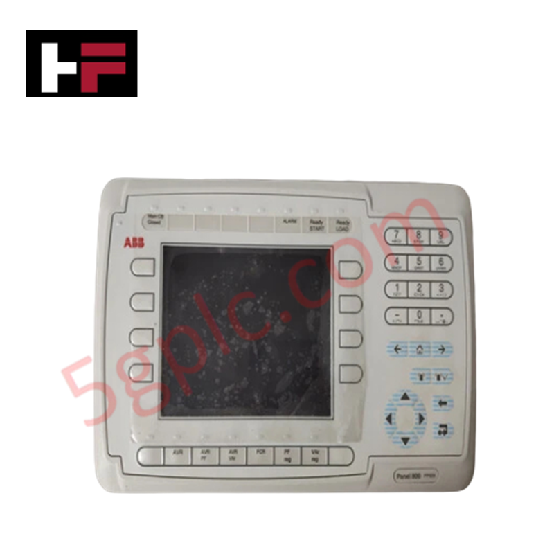
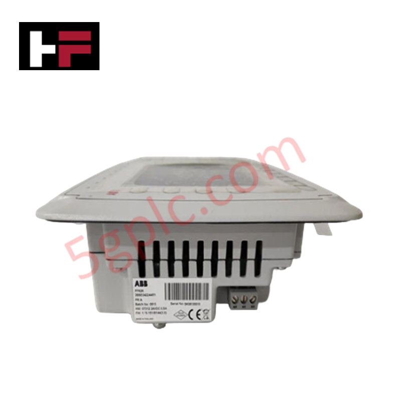
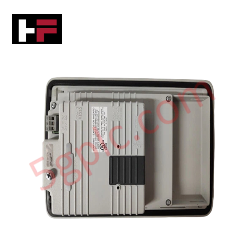
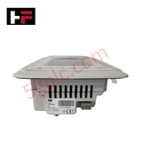
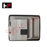
The ABB PP826 3BSE042244R1, also cataloged as the PP826 Control Panel, operates as a dedicated hardware component for human-machine interaction and physical signal monitoring within industrial process automation loops.
Hardware Specifications
| Parameter | Specification |
|---|---|
| Model | PP826 (3BSE042244R1) |
| Brand | ABB |
| Origin | Sweden |
| Weight | 1.11 kg |
| Dimensions | 275 mm x 168 mm x 57 mm (Front Panel) |
| Cut-Out Dimensions | 240 mm x 130 mm |
| Mounting Depth | 57 mm |
| Operating Temp | 0 deg C to +50 deg C nominal |
| Power Consumption | 0.3 A (Normal) / 0.5 A (Maximum) |
| Display Type | 5.7-inch STN/TFT color graphics display |
| Resolution | 320 x 240 pixels |
| Interface Layout | 16 programmable function keys with 16 dual-color LEDs |
Backplane Bus Communication Velocity and Firmware Flash Compatibility
The PP826 interfaces with master controllers using a defined serial or Ethernet communication interface, ensuring optimal bus data transfer rates across local networks. Visual state monitoring and register mappings scale evenly with system runtime demands. During field deployment, the firmware flash compatibility matrix requires verification to match the specific master station operating system software version. When updating the operational application file, internal processing speeds remain synchronized with the communication bus frame rates, eliminating data packet latency and maintaining high-frequency parameter display refreshes.
Frequently Asked Questions
Q: Does the PP826 operator interface support hot-swap replacement while the network bus is live?
A: Removing the auxiliary serial or Ethernet link will not damage the electrical integrity of the controller bus line, but it will immediately interrupt data scanning frames. The master controller will flag an interface drop alarm, and the unit must be offline during mechanical installation to prevent signal transients.
Q: How do the 16 programmable function keys draw power through the display logic?
A: The internal processing circuit supplies voltage to the dual-color LEDs based on register logic bits received from the controller. The maximum total power consumption of 0.5 A accounts for all 16 indicators illuminated concurrently alongside full backlight operation.
Field Installation Guidelines
- Panel Cut-Out Tolerances: Verify that the enclosure opening conforms exactly to the 240 mm x 130 mm dimensions. Deburr all cut edges to prevent localized stress points from cracking the perimeter sealing gasket.
- Mechanical Clamping Tension: Insert the unit into the cutout and tighten the rear mounting clamps progressively. Apply balanced torque to compress the front-panel bezel against the cabinet door to protect internal circuit cards from particulate matter.
- Power Conductor Termination: Connect the power leads to the designated terminal block using standard industrial wiring practices. Maintain strict separation between low-voltage logic power lines and high-current AC motor drive circuits.
- Shield and Earth Ground Bonding: Secure the dedicated frame ground terminal to the main panel earth bar. Ensure a low-impedance ground path to shield the display elements and data registers from external electromagnetic fields.
Additional Information
- 100% Genuine Parts: All products are original and authentic, ensuring reliable industrial performance.
- 30-Day Refund Guarantee: Return any in-stock item within 30 days in original, unopened packaging for a full refund (excluding shipping and fees).
- 12-Month Warranty: Covers defects in materials or workmanship; excludes misuse, normal wear, or unauthorized modifications.
- Worldwide Shipping: We ship via USPS, UPS, FedEx, and DHL. Delivery times vary by country and may be subject to customs or import fees.
- Support & Contact: Technical and warranty assistance is available anytime. Contact us here: Contact.
- Purchase Guidance: Check product specifications and compatibility carefully before ordering to ensure proper application.









Tech & Buying Guide

Mastering the Siemens PLC Scan Cycle: How the CPU Executes Automation Programs
Industrial automation relies heavily on programmable logic controllers (PLCs) to manage complex manufacturing processes. Many engineers dive straight into programming without mastering the underlying architecture. However, understanding how a PLC CPU executes a program ensures reliable system design. Therefore, mastering the scan cycle optimizes both performance and troubleshooting in modern control systems.

How to Connect to Siemens S7 PLCs: 5 Essential Communication Methods
Establishing a reliable hardware link between a programming terminal and a Siemens SIMATIC controller is essential for engineering workflows. Field engineers rely on distinct physical layers, ranging from legacy serial connections to high-speed Industrial Ethernet protocols. Modern factory automation environments prioritize fast data transfer and seamless driver integration. Selecting the correct connection method simplifies program downloads, online monitoring, and system troubleshooting in complex control systems.

Will PLCs Become Obsolete? The Future of Control Systems in Industry 4.0
Modern manufacturing is undergoing a rapid technological transformation driven by Industry 4.0 innovations. Technologies like Artificial Intelligence (AI), Machine Learning (ML), and the Industrial Internet of Things (IIoT) are dominating discussions across the factory automation sector. Consequently, many engineers wonder if these advanced digital tools will eventually replace traditional Programmable Logic Controllers (PLCs). However, evaluating the core physics of industrial operations reveals a very different reality for control systems.