










Product Details
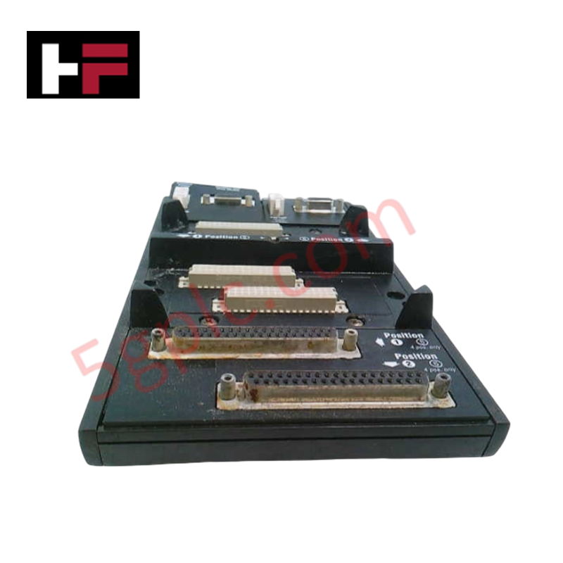
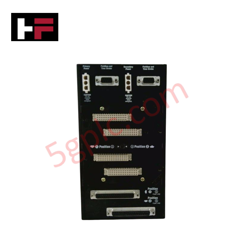
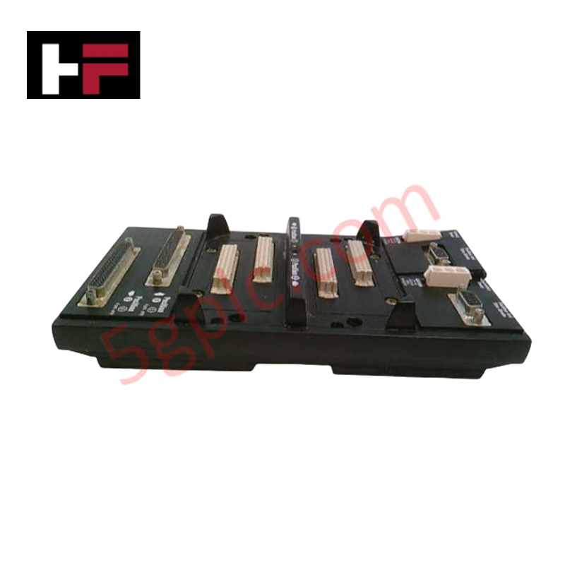
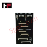
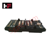
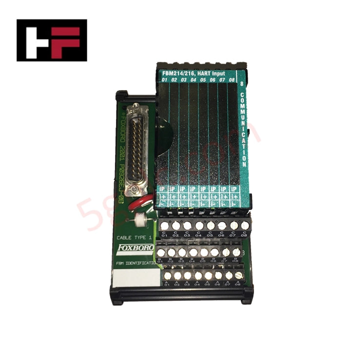
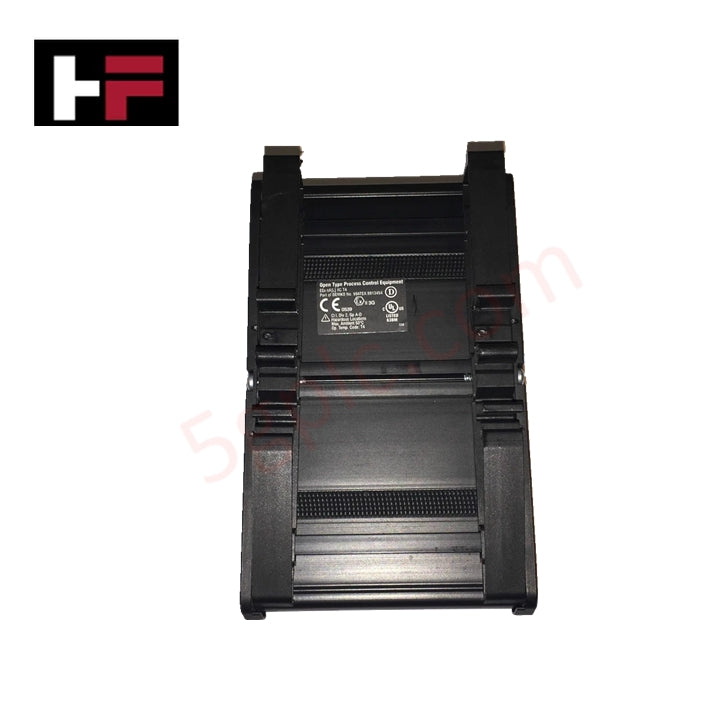
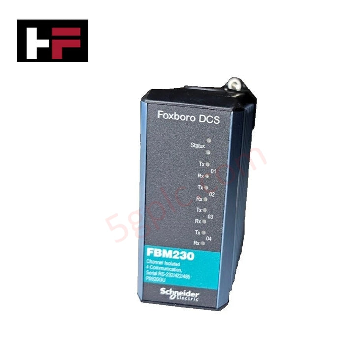
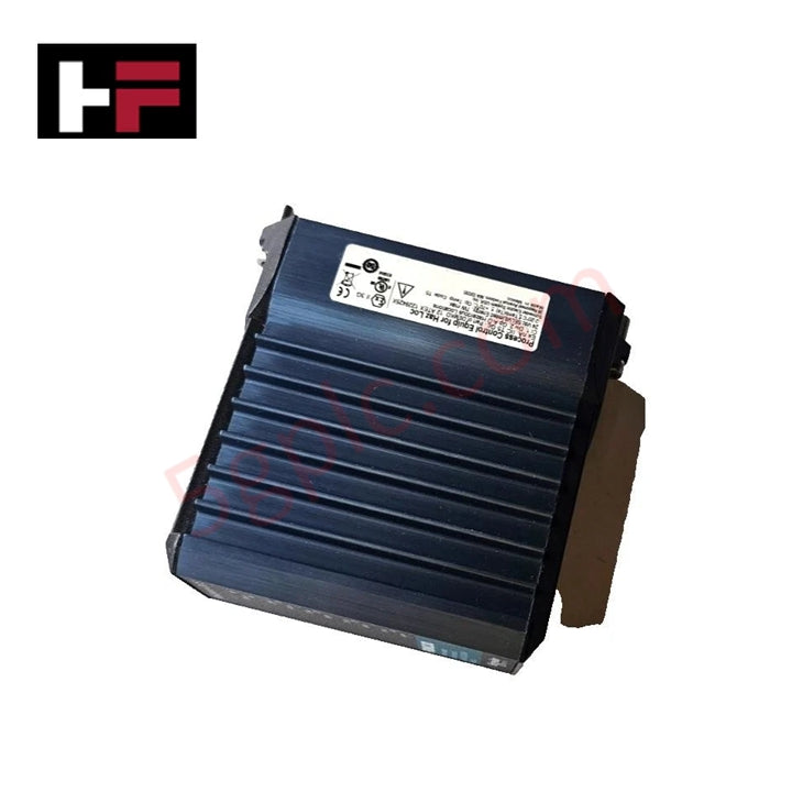
The Foxboro P0926HM, also cataloged as the P0926HM Horizontal Baseplate Time Stroke Module, operates as a dedicated hardware component for time strobe signal synchronization and power distribution within Foxboro I/A Series platforms. It accommodates up to four Fieldbus Modules (FBMs) across a horizontal mounting format to coordinate real-time control actions and bus communications.
Hardware Specifications
| Parameter | Specification |
|---|---|
| Model | P0926HM |
| Brand | Foxboro |
| Origin | USA |
| Weight | 0.6 kg |
| Dimensions | 14.7 cm x 5.15 cm x 11.4 cm |
| Operating Temp | 0 deg C to +60 deg C |
| Power Consumption | Maximum 8.5 W per non-fault-tolerant module |
| Slot Capacity | 4 Fieldbus Module (FBM) slots |
| Operating Voltage | 24 VDC (redundant) |
| Mounting Orientation | Horizontal |
Process Loop Signal Conditioning and Channel Isolation
The Foxboro P0926HM utilizes dedicated internal isolation pathways to shield high-frequency time strobe pulses from field-side loop interference. By maintaining clean channel-to-channel isolation across the 24 VDC power rail and backplane signal traces, the baseplate prevents common-mode noise propagation, preserving 4-20 mA HART loop protocol signal integrity across all four attached FBM slots.
Frequently Asked Questions
Q: How is power redundancy implemented across the four module slots on the P0926HM?
A: The baseplate contains dual independent 24 VDC power distribution tracks with integrated diode decoupling, enabling uninterrupted module execution during a single power supply failure.
Q: Can Fieldbus Modules installed on the P0926HM baseplate be live-swapped during active system processing?
A: Yes, the baseplate supports hot-swapping of compatible FBMs, permitting module replacement without interrupting time strobe signals or communication traffic on adjacent slots.
Field Installation Guidelines
Secure the baseplate horizontally onto the cabinet mounting surface using appropriate fasteners. Ensure the chassis ground connection makes solid metal-to-metal contact with an unpainted, conductive backpanel to establish a low-impedance path to earth ground. Maintain at least 50 mm of vertical clearance above and below the assembly for unimpeded natural thermal convection.
Connect redundant 24 VDC power lines using separate, fused power feeds. Run all field communications and time strobe wiring using shielded twisted-pair cables, bonding the shield drain wires to a central grounding bar. When routing cables through panel entries, ensure standard NPT fittings achieve at least 5 full threads of engagement to preserve cabinet enclosure integrity.
Additional Information
- 100% Genuine Parts: All products are original and authentic, ensuring reliable industrial performance.
- 30-Day Refund Guarantee: Return any in-stock item within 30 days in original, unopened packaging for a full refund (excluding shipping and fees).
- 12-Month Warranty: Covers defects in materials or workmanship; excludes misuse, normal wear, or unauthorized modifications.
- Worldwide Shipping: We ship via USPS, UPS, FedEx, and DHL. Delivery times vary by country and may be subject to customs or import fees.
- Support & Contact: Technical and warranty assistance is available anytime. Contact us here: Contact.
- Purchase Guidance: Check product specifications and compatibility carefully before ordering to ensure proper application.
Tech & Buying Guide

Redefining Control Systems: The Rise of Flexible I/O Modules in Industrial Automation
Conventional input-output architectures often limit engineering agility and inflate long-term inventory costs. Today, Flexible Input/Output Modules (FIOM) are transforming how control system engineers design, commission, and maintain automation infrastructure. By allowing individual channel software configuration, FIOM technology bridges the gap between rigid hardware design and dynamic plant requirements.

Understanding Modern SCADA Systems: Architecture, Communication Topologies, and Industrial Applications
Supervisory Control and Data Acquisition (SCADA) systems form the digital backbone of modern industrial automation. They collect critical field data, transmit signals across vast distances, and empower plant operators with real-time process visibility. Across modern infrastructures, SCADA solutions streamline centralized control and maintain continuous operational uptime.
Understanding OPC Servers in Modern Industrial Automation: Principles, Architecture, and Applications
In industrial automation, connecting physical hardware with high-level software remains a primary operational challenge. Factories utilize programmable logic controllers (PLCs), distributed control systems (DCS), human-machine interfaces (HMIs), and smart sensors from diverse vendors. These devices often speak different proprietary protocols. Open Platform Communications (OPC) servers solve this interoperability challenge by standardizing how data flows across factory networks.