










Product Details
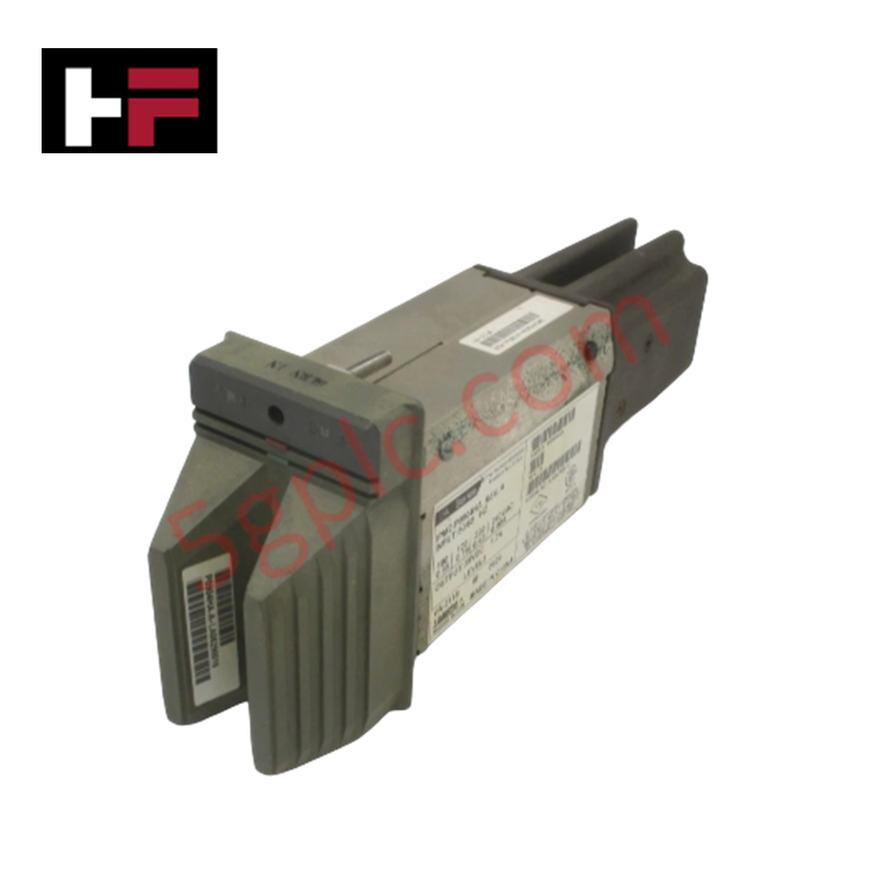
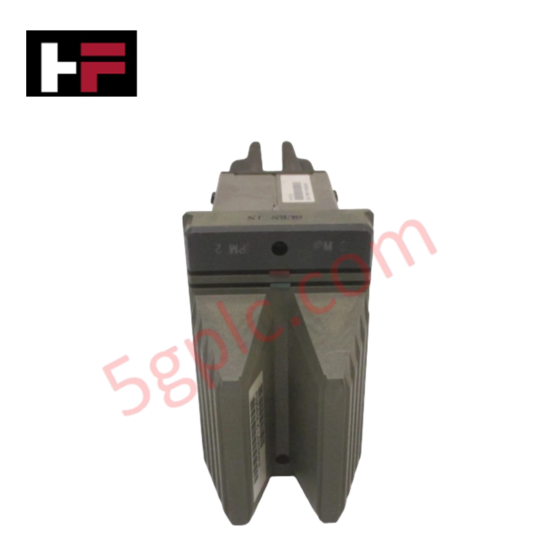
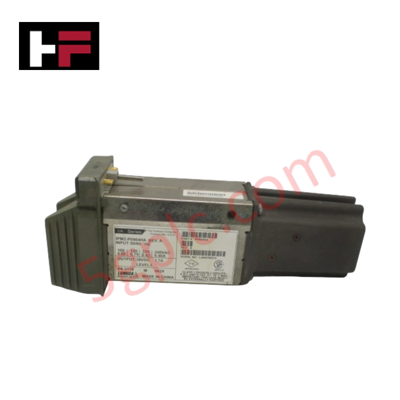
The Foxboro IPM2-P0904HA, also cataloged as the IPM2 Industrial Power Module, operates as a dedicated hardware component for AC to DC power conversion within Foxboro I/A Series DCS racks. Configured to receive selectable 100/120/220/240 VAC mains input, it delivers a regulated 39 VDC output bus to drive system logic backplanes and fieldbus interface assemblies.
Hardware Specifications
| Parameter | Specification |
|---|---|
| Model | IPM2-P0904HA |
| Brand | Foxboro |
| Origin | USA |
| Weight | Standard power module weight |
| Dimensions | Sub-rack power bay enclosure unit |
| Operating Temp | -20 deg C to +70 deg C |
| Power Consumption | Input AC power source dependent |
| Input Voltage | 100 / 120 / 220 / 240 VAC selectable |
| Output Voltage | 39 VDC |
| Output Power | Up to 20 kW nominal output |
| Status Monitoring | Front panel LED indicators |
Process Loop Signal Conditioning and Channel Isolation
The Foxboro IPM2-P0904HA incorporates primary-to-secondary galvanic isolation to protect backplane communication links from grid-side transients. By decoupling the AC power source from the internal 39 VDC power distribution rail, the module suppresses ground loops and high-frequency noise that could otherwise impair 4-20 mA HART loop protocol accuracy across connected analog field channels.
Frequently Asked Questions
Q: Can the 39 VDC output bus operating voltage be adjusted manually on the module?
A: No, the output voltage is internally regulated to 39 VDC to meet system sub-rack distribution tolerances. Input voltage selection must be configured via designated jumpers or terminal taps prior to applying AC power.
Q: What functions do the front panel status LEDs perform during routine operation?
A: The onboard LEDs provide continuous physical diagnostics, displaying AC input power availability, DC output health, and internal thermal or over-current fault conditions.
Field Installation Guidelines
Ensure AC supply breakers are locked out and verified zero-energy before connecting incoming power to the primary input terminals. Select the correct input tap setting (100, 120, 220, or 240 VAC) corresponding to local utility power standards prior to energization.
Maintain a minimum physical clearance of 100 mm above and below the power module frame to facilitate uninhibited natural convection airflow through the enclosure heat sinks. Connect the module chassis grounding terminal directly to the main enclosure protective earth (PE) bus bar using a heavy-gauge copper conductor. For cabinet entry, verify all NPT conduit connections maintain a minimum 5-thread engagement to ensure structural and electrical grounding integrity.
Additional Information
- 100% Genuine Parts: All products are original and authentic, ensuring reliable industrial performance.
- 30-Day Refund Guarantee: Return any in-stock item within 30 days in original, unopened packaging for a full refund (excluding shipping and fees).
- 12-Month Warranty: Covers defects in materials or workmanship; excludes misuse, normal wear, or unauthorized modifications.
- Worldwide Shipping: We ship via USPS, UPS, FedEx, and DHL. Delivery times vary by country and may be subject to customs or import fees.
- Support & Contact: Technical and warranty assistance is available anytime. Contact us here: Contact.
- Purchase Guidance: Check product specifications and compatibility carefully before ordering to ensure proper application.
Tech & Buying Guide

Redefining Control Systems: The Rise of Flexible I/O Modules in Industrial Automation
Conventional input-output architectures often limit engineering agility and inflate long-term inventory costs. Today, Flexible Input/Output Modules (FIOM) are transforming how control system engineers design, commission, and maintain automation infrastructure. By allowing individual channel software configuration, FIOM technology bridges the gap between rigid hardware design and dynamic plant requirements.

Understanding Modern SCADA Systems: Architecture, Communication Topologies, and Industrial Applications
Supervisory Control and Data Acquisition (SCADA) systems form the digital backbone of modern industrial automation. They collect critical field data, transmit signals across vast distances, and empower plant operators with real-time process visibility. Across modern infrastructures, SCADA solutions streamline centralized control and maintain continuous operational uptime.
Understanding OPC Servers in Modern Industrial Automation: Principles, Architecture, and Applications
In industrial automation, connecting physical hardware with high-level software remains a primary operational challenge. Factories utilize programmable logic controllers (PLCs), distributed control systems (DCS), human-machine interfaces (HMIs), and smart sensors from diverse vendors. These devices often speak different proprietary protocols. Open Platform Communications (OPC) servers solve this interoperability challenge by standardizing how data flows across factory networks.