










Product Details
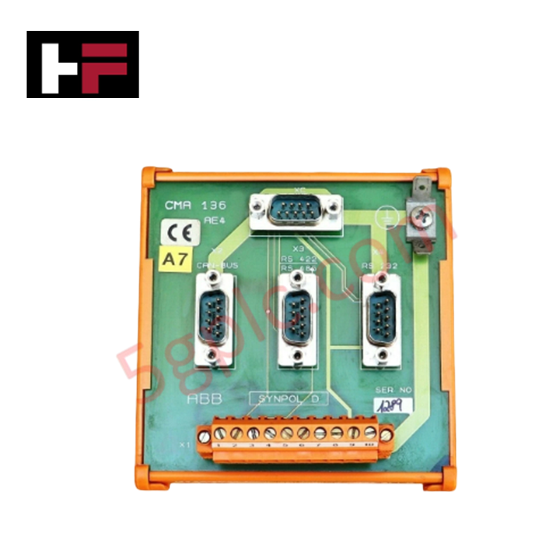
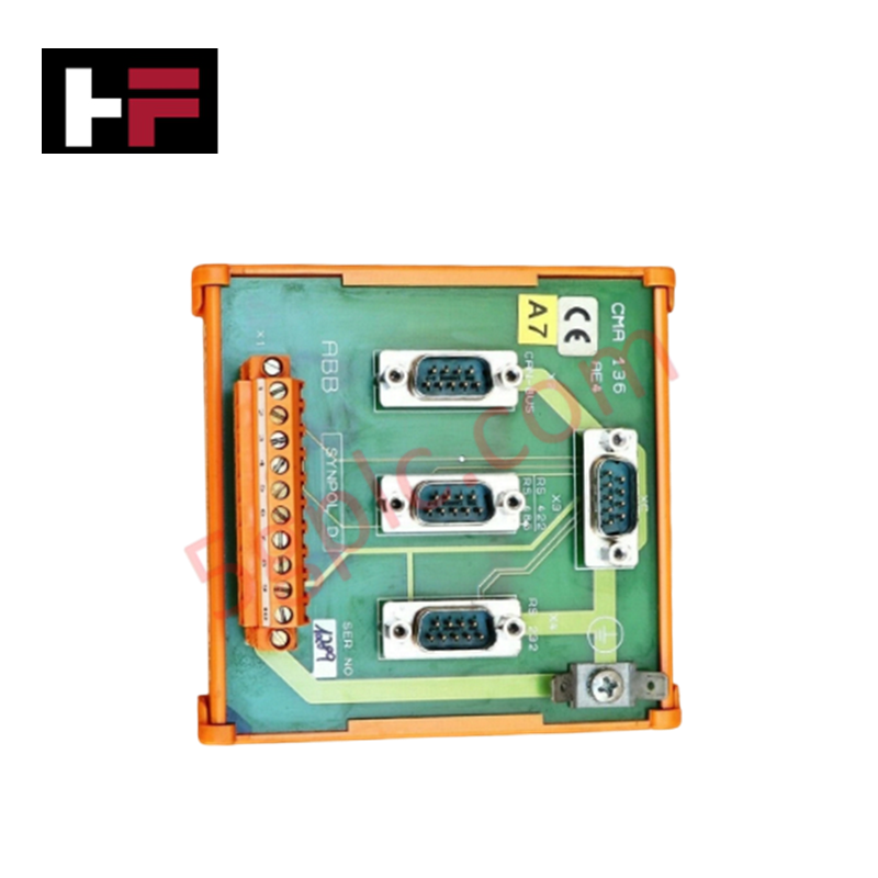
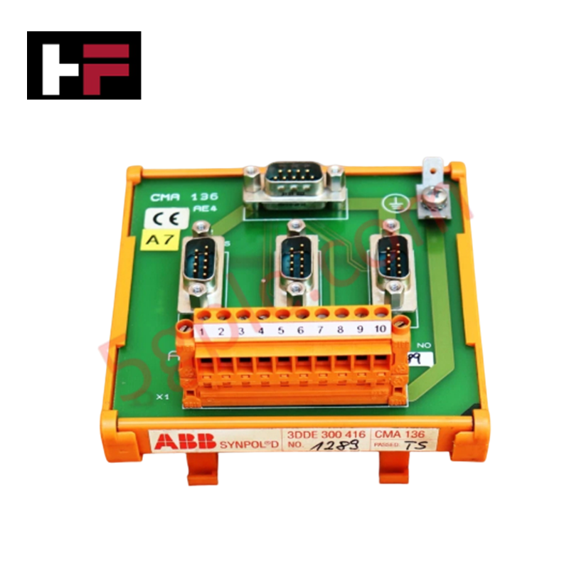
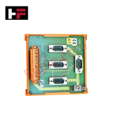
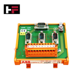
Configured for discrete generator trip execution and status feedback in Synpol D generator control architectures, the ABB CMA 136 3DDE 300 416 (CMA136 Terminal Board) provides direct physical/electrical execution.
Hardware Specifications
| Parameter | Specification |
|---|---|
| Model | CMA 136 (3DDE 300 416) |
| Brand | ABB |
| Origin | Sweden |
| Weight | 0.5 kg |
| Dimensions | 127 mm x 102 mm x 178 mm |
| Operating Temp | -20 to +60 deg C |
| Power Consumption | 24 VDC control power (dual input terminals for redundant power) |
| Relay Channels | 16 independent SPDT relay outputs (10 A per channel, 120-240 VAC) |
| Communication Protocols | RS-232, RS-485, Modbus RTU/TCP, PROFIBUS DP |
| Processing Unit | ARM Cortex-M4 (180 MHz), 128 KB SRAM, 2 MB Flash |
| Protection Rating | IP20 |
Backplane Bus Communication Velocity and I/O Density Scaling
The CMA 136 terminal board maintains high I/O density scaling by executing discrete relay switching across 16 SPDT channels without degrading backplane bus communication velocity across system subracks. Real-time signal updates processed through the embedded ARM Cortex-M4 core ensure synchronized output switching across PROFIBUS DP and Modbus network links. Deterministic response times prevent communication lag during multi-channel protection trips.
Frequently Asked Questions
Q: What contact rating is supported on the individual relay channels of the CMA136 module?
A: Each of the 16 independent SPDT relay channels is rated to switch loads up to 10 A across a 120-240 VAC output range.
Q: How is power redundancy handled on the terminal board?
A: The board features dual 24 VDC input terminals, permitting connection to redundant control supply buses to prevent power failure shutdowns.
Q: Which field communication protocols can be interfaced directly via the onboard ports?
A: The board supports serial RS-232 and RS-485 interfaces running Modbus RTU or PROFIBUS DP, as well as Ethernet-based Modbus TCP.
Field Installation Guidelines
- De-energize all 120-240 VAC load circuits and disconnect 24 VDC control power prior to installation or wiring tasks.
- Maintain standard electrostatic discharge (ESD) precautions, including the use of a grounded wrist strap, when handling the terminal board.
- Secure the module onto a standard mounting track, ensuring full engagement of the IP20 chassis housing.
- Wire field output loads using copper conductors rated for 10 A per channel, ensuring screw terminals are torque-tightened to specification.
- Connect dual 24 VDC supply lines to the redundant input terminals and establish earth ground continuity through the mounting base.
Additional Information
- 100% Genuine Parts: All products are original and authentic, ensuring reliable industrial performance.
- 30-Day Refund Guarantee: Return any in-stock item within 30 days in original, unopened packaging for a full refund (excluding shipping and fees).
- 12-Month Warranty: Covers defects in materials or workmanship; excludes misuse, normal wear, or unauthorized modifications.
- Worldwide Shipping: We ship via USPS, UPS, FedEx, and DHL. Delivery times vary by country and may be subject to customs or import fees.
- Support & Contact: Technical and warranty assistance is available anytime. Contact us here: Contact.
- Purchase Guidance: Check product specifications and compatibility carefully before ordering to ensure proper application.









Tech & Buying Guide

The Shift to Flexible IO Modules in Modern Industrial Automation
Traditional control systems rely on dedicated Input Output (IO) cards for industrial automation. Each conventional module processes a single signal type, such as Digital Input (DI), Digital Output (DO), Analog Input (AI), or Analog Output (AO). A standard 16-channel card accepts only one specific channel type across all ports. This inflexible hardware design often creates severe engineering bottlenecks during project execution. Engineers frequently must install entirely new cards to accommodate a single extra sensor. Consequently, late design changes increase control cabinet space requirements and drive up project costs.

DCS Commissioning Steps in Industrial Automation Projects
Commissioning a Distributed Control System (DCS) represents a crucial milestone when deploying modern process automation infrastructure. Field engineers must execute systematic verification steps to transition complex control hardware from static installation to dynamic plant control. Proper commissioning ensures that controllers, I/O modules, network switches, and HMI software operate in strict compliance with engineering design specifications before introducing live process fluids.

PLC and DCS Control System Spares Strategy: Engineering Guidelines
Modern factory automation relies on high-speed fiber optic backbones to link distributed control systems across noise-intensive industrial environments. Unlike copper wiring, optical fibers transmit data via light pulses, making them completely immune to electromagnetic interference (EMI). Field engineers must master optical cable joining and fusion splicing techniques to guarantee low-loss data transmission across critical Programmable Logic Controller (PLC) and Distributed Control System (DCS) nodes.