Product Details
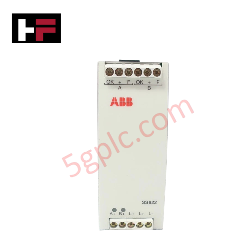
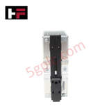
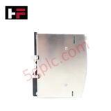
Configured for power redundancy and voting execution in 24 VDC distribution networks, the ABB SS822 3BSC610068R1 (SS822 Voter Unit) provides direct physical/electrical execution. It handles dual power supply inputs to ensure uninterrupted continuous operation across critical control loops, preventing system shut downs caused by single-point power source failures through direct diode auctioneering and real-time status supervision.
Hardware Specifications
| Parameter | Specification |
|---|---|
| Model | SS822 3BSC610068R1 |
| Brand | ABB |
| Origin | Sweden |
| Weight | 350 g (0.77 lbs.) |
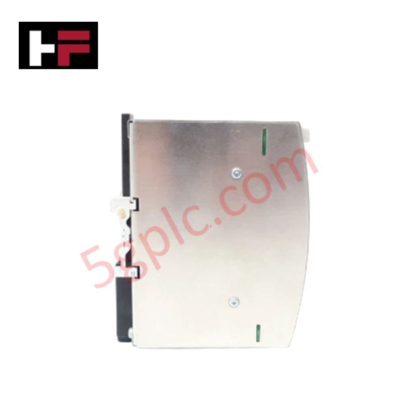
| Dimensions | 32 mm x 125 mm x 117 mm (1.26 in x 4.90 in x 4.61 in) |
| Operating Temp | 55 deg C max |
| Power Consumption | Heat dissipation: 18 W |
| Module Type | Power Supply Voter Unit |
| Rated Input Current | 2 x 10 A |
| Nominal Input Voltage | 2 x 24 VDC |
| Maximum Input Voltage | 60 VDC |
| Rated Output Current | 10 A (20 A in parallel operation) |
| Maximum Output Current | 25 A (Overload) |
| Output Voltage Drop | 0.85 V typ. at max. current |
| Short Circuit Limit | Max 25 A RMS |
| Supervision Relay | Integrated (Yes) |
| Mounting Spacing | Width: 15 mm (0.59 in), Height: 25 mm (1.00 in) |
Power Supply Redundancy and Backplane Bus Velocity Integration
The ABB SS822 voter unit acts as an essential decoupling component within high-availability control architectures. Designed to seamlessly interface alongside System 800xA rail-mounted power systems, the unit utilizes low-forward-voltage Schottky diode arrays to minimize internal heat dissipation (18 W maximum) while preventing back-feeding into a faulted input supply. Its integrated supervision relay continuously monitors input voltage thresholds, instantly signaling status changes across backplane bus communication velocity networks and I/O channels without introducing latency or deterministic network jitter to the primary CPU controller.
Frequently Asked Questions
Q: What is the maximum current rating when operating two SS822 units or input paths in parallel?
A: The rated output current is 10 A for single-channel operation, expanding up to 20 A when operated in parallel configuration under standard 55 deg C thermal limits.
Q: How does the SS822 indicate a power supply failure on one of its dual inputs?
A: The module contains an integrated supervision relay with dry contacts that toggle state when an input rail drops below operational voltage limits, enabling direct connection to PLC alarm digital inputs.
Q: What is the maximum voltage drop across the SS822 voting module during full load?
A: The typical output voltage regulation drop across internal decoupling components is 0.85 VDC at maximum continuous rated load current.
Field Installation Guidelines
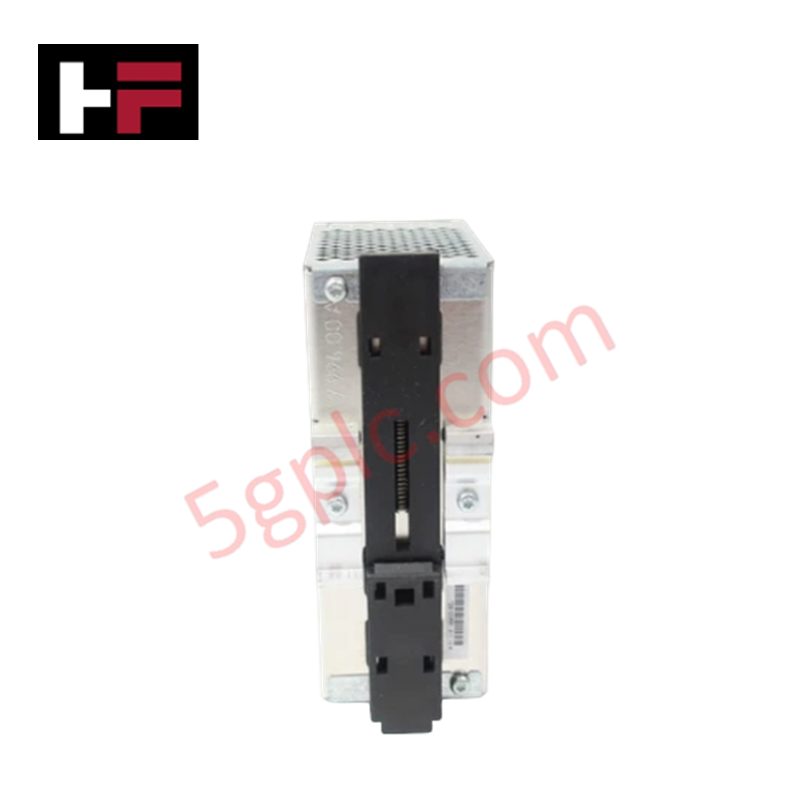
- DIN-Rail Mounting and Thermal Clearance: Mount the SS822 unit vertically onto standard EN 60715 DIN rail (35 mm). Maintain a minimum clearance spacing of 15 mm horizontally between adjacent modules and 25 mm vertically above and below the unit to ensure adequate natural convective air flow for heat dissipation.
- Wiring and Cable Shielding: Utilize copper conductors rated for at least 75 deg C. Strip wire ends according to terminal block specification (typically 7 mm) and torque terminal screws appropriately. Route incoming 24 VDC dual supply cables in separate wire ducts away from high-voltage AC lines or fast-transient switching circuits to avoid induced EMI.
- Grounding and Earth Bonding: Ensure direct metallic contact between the module DIN-rail mounting clip and the grounded backplate. Connect the system protective earth (PE) busbar directly to the panel chassis with low-impedance ground straps.
- Relay Supervision Hookup: Wire the supervision relay contact terminals to a monitored 24 VDC digital input channel on the DCS/PLC I/O rack. Verify contact continuity prior to powering the primary and secondary 24 VDC power supply channels.
Additional Information
- 100% Genuine Parts: All products are original and authentic, ensuring reliable industrial performance.
- 30-Day Refund Guarantee: Return any in-stock item within 30 days in original, unopened packaging for a full refund (excluding shipping and fees).
- 12-Month Warranty: Covers defects in materials or workmanship; excludes misuse, normal wear, or unauthorized modifications.
- Worldwide Shipping: We ship via USPS, UPS, FedEx, and DHL. Delivery times vary by country and may be subject to customs or import fees.
- Support & Contact: Technical and warranty assistance is available anytime. Contact us here: Contact.
- Purchase Guidance: Check product specifications and compatibility carefully before ordering to ensure proper application.









Tech & Buying Guide

Voice-Activated Industrial Automation: Integrating Speech Control into PLC and DCS Architectures
Industrial automation integrates speech recognition, IIoT protocols, and NLP with PLCs and DCS to streamline operations. By leveraging advanced edge computing, engineers enable real-time, hands-free control—allowing personnel to manage smart factory processes safely away from hazardous equipment.

Modern Industrial Automation: Transforming Safety and Efficiency in Mining Operations
Industrial automation has evolved from a simple manufacturing tool into the operational backbone of high-risk sectors. Modern mining operations increasingly rely on advanced control systems, programmable logic controllers (PLCs), distributed control systems (DCS), and artificial intelligence to address deep-underground hazards. By replacing manual labor in high-risk zones, factory automation technologies protect personnel while significantly boosting operational throughput.