










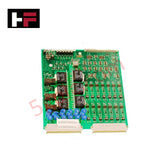
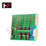
Product Details
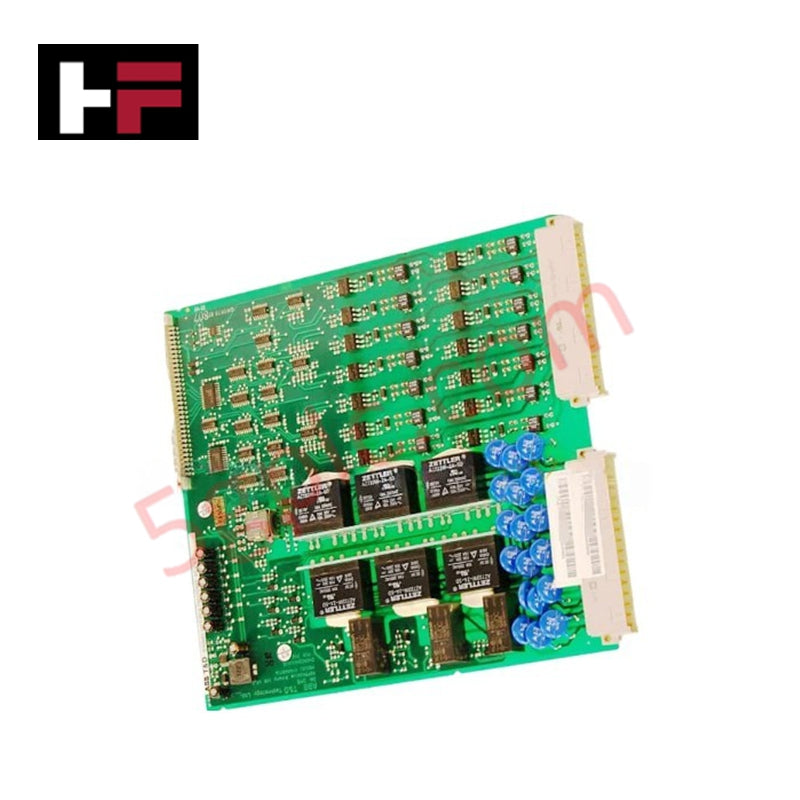
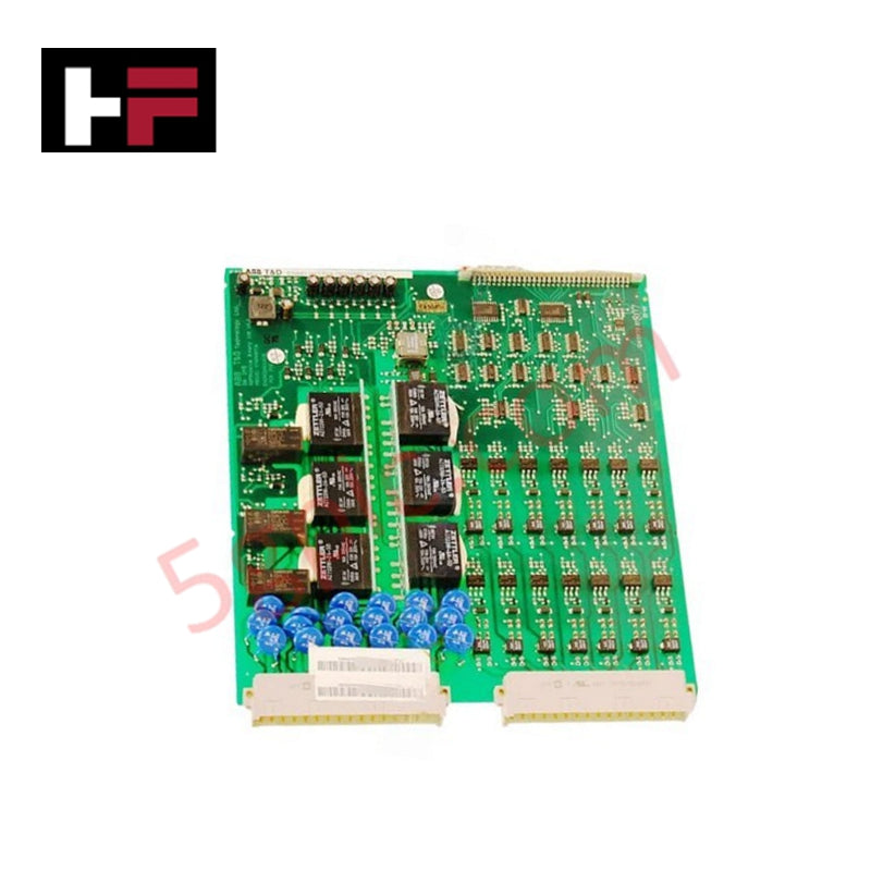
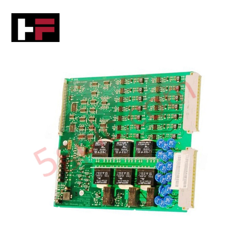
Configured for discrete signal scanning and logic execution in industrial control nodes, the ABB 1VCF750132807 (BIO3 176-264VDC (143VDC) Input/Output Module) provides direct physical/electrical execution.
Hardware Specifications
| Parameter | Specification |
|---|---|
| Model | 1VCF750132807 |
| Brand | ABB |
| Origin | Sweden |
| Weight | 0.46 kg net |
| Dimensions | Standard grid allocation width for BIO3 module subracks |
| Operating Temp | -10 deg C to +55 deg C nominal |
| Power Consumption | Dependent on active loop load constraints |
| Voltage Range | 176 VDC to 264 VDC operational window |
| Threshold Voltage | 143 VDC activation threshold limit |
| Product Type | Binary input/output processing module (Spare part) |
Backplane Bus Communication Velocity and System Clock Sync
The 1VCF750132807 interfaces with the node controller across high-density connection pins that maintain uniform backplane bus communication velocity. The binary module maps physical high-voltage contact inputs directly to internal memory arrays within fixed microsecond cycles. Hardware filtering circuits suppress transients and mechanical contact bounce across the 176-264 VDC operational window, preventing signal noise from interrupting the real-time deterministic software task. By implementing physical I/O density scaling options across localized racks, the interface module transfers processed field status bits into local register structures simultaneously with the centralized system clock.
Frequently Asked Questions
Q: What is the technical behavior of the 143 VDC rating on the 1VCF750132807?
A: The 143 VDC specification dictates the physical switching threshold for the binary logic input circuits. Any applied field potential above 143 VDC forces the module log into a logic state of 1, whereas voltage drops substantially beneath this marker cause the input channel to transition back to a logic state of 0.
Q: Can the 1VCF750132807 module be hot-swapped while the primary backplane is actively cycling data?
A: Physical insertion or extraction of this unit under active backplane power requires verification of the parent rack's design parameters. If the hardware frame lacks dedicated pre-charge grounding pin trails, removing the module can interrupt the localized internal bus velocity and trigger master chassis communication errors.
Field Installation Guidelines
- Subrack Insertion Mechanical Alignment: Align the top and bottom edge tracks of the 1VCF750132807 with the corresponding module slot guides within the subrack housing. Push the assembly inward until the rear pins seat completely into the backplane matrix.
- Terminal Wire Connection Integrity: Fasten the high-voltage discrete loop wires into the dedicated terminal block matching the module layout. Maintain firm terminal screw retention to lower contact resistance across the 176-264 VDC voltage paths.
- Common Return Grounding Protocol: Connect the system common and return paths to the appropriate bus terminations within the instrumentation cubicle. Do not share input returns with inductive power links to minimize electrical interference across sensor loops.
- Wiring Separations and Cable Management: Route high-voltage binary loop cables separate from low-voltage network trunks and fiber systems inside the enclosure wireways. This prevents high-voltage capacitive coupling from inducing stray voltages across deterministic networks.
Additional Information
- 100% Genuine Parts: All products are original and authentic, ensuring reliable industrial performance.
- 30-Day Refund Guarantee: Return any in-stock item within 30 days in original, unopened packaging for a full refund (excluding shipping and fees).
- 12-Month Warranty: Covers defects in materials or workmanship; excludes misuse, normal wear, or unauthorized modifications.
- Worldwide Shipping: We ship via USPS, UPS, FedEx, and DHL. Delivery times vary by country and may be subject to customs or import fees.
- Support & Contact: Technical and warranty assistance is available anytime. Contact us here: Contact.
- Purchase Guidance: Check product specifications and compatibility carefully before ordering to ensure proper application.









Tech & Buying Guide

Mastering the Siemens PLC Scan Cycle: How the CPU Executes Automation Programs
Industrial automation relies heavily on programmable logic controllers (PLCs) to manage complex manufacturing processes. Many engineers dive straight into programming without mastering the underlying architecture. However, understanding how a PLC CPU executes a program ensures reliable system design. Therefore, mastering the scan cycle optimizes both performance and troubleshooting in modern control systems.

How to Connect to Siemens S7 PLCs: 5 Essential Communication Methods
Establishing a reliable hardware link between a programming terminal and a Siemens SIMATIC controller is essential for engineering workflows. Field engineers rely on distinct physical layers, ranging from legacy serial connections to high-speed Industrial Ethernet protocols. Modern factory automation environments prioritize fast data transfer and seamless driver integration. Selecting the correct connection method simplifies program downloads, online monitoring, and system troubleshooting in complex control systems.

Will PLCs Become Obsolete? The Future of Control Systems in Industry 4.0
Modern manufacturing is undergoing a rapid technological transformation driven by Industry 4.0 innovations. Technologies like Artificial Intelligence (AI), Machine Learning (ML), and the Industrial Internet of Things (IIoT) are dominating discussions across the factory automation sector. Consequently, many engineers wonder if these advanced digital tools will eventually replace traditional Programmable Logic Controllers (PLCs). However, evaluating the core physics of industrial operations reveals a very different reality for control systems.