










Product Details
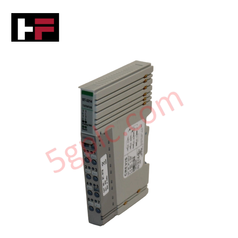
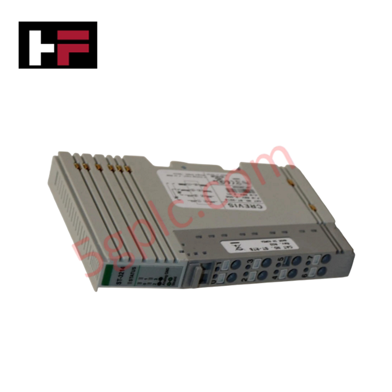
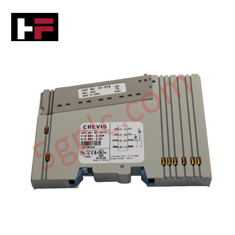
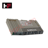
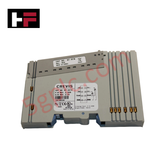
The GE ST-3214, also cataloged as the ST-3214 Analog Input Module, operates as a dedicated hardware component for analog loop signal processing within RSTi Series network platforms.
Hardware Specifications
| Parameter | Specification |
|---|---|
| Model | ST-3214 |
| Brand | GE / GE Fanuc |
| Origin | United States |
| Weight | Standard Slice Component Weight |
| Dimensions | Compact RSTi Slice Form Factor |
| Operating Temp | 0 - 55 deg C |
| Power Consumption | 165 mA @ 5 VDC |
| Channels | 4 channels |
| Input Range | 4-20 mA |
| Resolution | 12-bit |
| Conversion Speed | 4 ms |
| Data Interface | Ethernet-based slice I/O |
Firmware Flash Compatibility and Slice Communication
The module interfaces 4 discrete 4-20 mA current loops directly to an Ethernet-based slice I/O system, enabling rapid processing frames across the backplane network. To ensure proper signal alignment and prevent data corruption, matching the active module layer with appropriate firmware flash compatibility settings on the head network adapter is required. The localized logic transforms the current signals into 12-bit digital values every 4 ms, which are then transmitted to the central controller register maps over deterministic bus topologies.
Frequently Asked Questions
Q: Does the ST-3214 module permit hot-swapping or live insertion on an active terminal base?
A: No. The RSTi slice bus connector lacks staggered power pin layouts or transient isolation suppression circuits. Removing or inserting the module while the backplane power rail is energized will trigger logic interface faults and risk component failure.
Q: How is the internal 165 mA @ 5 VDC power consumption load managed across the slice assembly?
A: This current is drawn directly from the 5 VDC system bus provided by the network adapter or the auxiliary power supply module. System designers must calculate total slice accumulation to ensure the internal power rail threshold is not exceeded.
Field Installation Guidelines
- Base Mounting Mechanics: Position the slice module within the terminal base guide grooves, pushing downward onto the DIN-rail arrangement until the mechanical latches lock into position.
- Current Loop Cable Separation: Route all 4-20 mA instrument cables through low-voltage raceways isolated from alternating current (AC) motor feeds and switching control lines.
- Shield Interconnection Framework: Terminate the instrument cable shields to a dedicated, low-impedance earth ground busbar inside the local enclosure panel to ensure 12-bit conversion integrity.
Additional Information
- 100% Genuine Parts: All products are original and authentic, ensuring reliable industrial performance.
- 30-Day Refund Guarantee: Return any in-stock item within 30 days in original, unopened packaging for a full refund (excluding shipping and fees).
- 12-Month Warranty: Covers defects in materials or workmanship; excludes misuse, normal wear, or unauthorized modifications.
- Worldwide Shipping: We ship via USPS, UPS, FedEx, and DHL. Delivery times vary by country and may be subject to customs or import fees.
- Support & Contact: Technical and warranty assistance is available anytime. Contact us here: Contact.
- Purchase Guidance: Check product specifications and compatibility carefully before ordering to ensure proper application.


Tech & Buying Guide
Comprehensive Guide to PLC Types in Modern Industrial Automation
Modern industrial automation relies on programmable logic controllers to govern critical factory operations. System integrators classify PLCs based on scale, hardware architecture, and power supply design. Understanding these core categories enables automation engineers to select the right control system architecture. Consequently, proper hardware selection optimizes performance while minimizing long-term operational costs.

Demystifying the DDE Protocol in Legacy Industrial Automation Systems
Modern control systems rely heavily on seamless interprocess communication to exchange operational data between software programs. Microsoft first introduced the Dynamic Data Exchange (DDE) protocol in 1987 to enable real-time data sharing. In factory automation, DDE served as an early bridge between control software and Windows desktop applications. Therefore, understanding DDE mechanics provides crucial insights into how legacy industrial networks established software-level connectivity.

Demystifying CPU Communication Ports in Siemens PLC Architectures
Industrial automation relies heavily on robust data exchange between devices. Without seamless connectivity, field instruments, network switches, human-machine interfaces, and programmable logic controllers cannot coordinate effectively. Therefore, understanding the various CPU communication ports available in Siemens hardware ensures efficient factory automation design and seamless system integration.