










Product Details
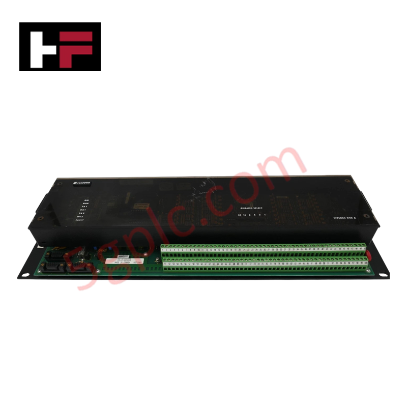
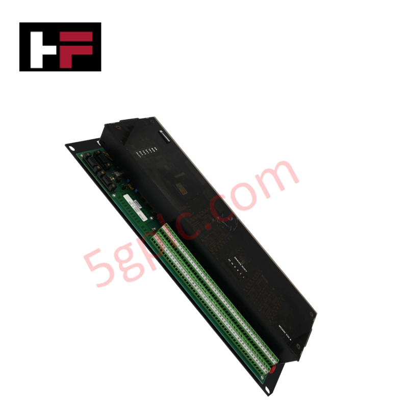
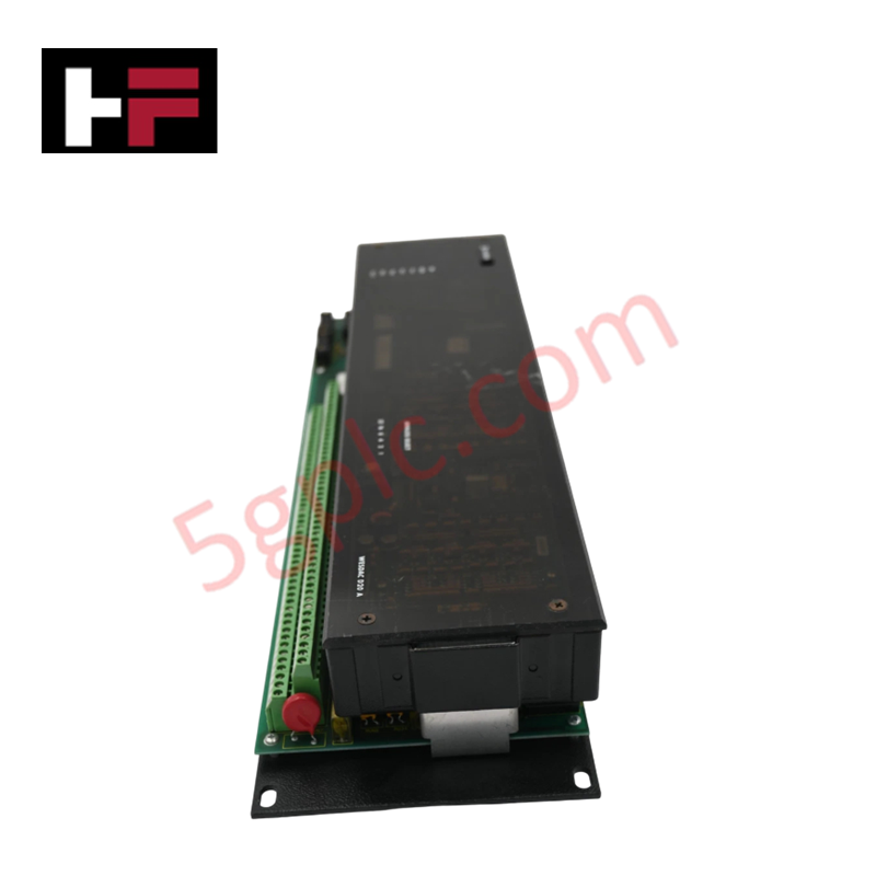
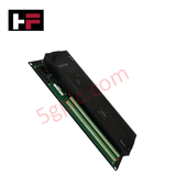
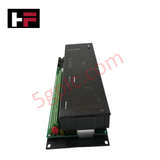
The GE WESDAC D20A, also cataloged as the WESDAC D20A Analog Scan Module, operates as a dedicated hardware component for multi-channel analog signal acquisition within WESDAC D20 automation architectures.
Hardware Specifications
| Parameter | Specification |
|---|---|
| Model | WESDAC D20A |
| Brand | GE (General Electric) |
| Origin | United States |
| Weight | Standard D20 Series Module Weight Profile |
| Dimensions | Two-Module Detachable Chassis Assembly |
| Operating Temp | Standard Substation Operating Temperature Range |
| Power Consumption | Internal Baseplate Logic Dependent |
| Input Channels | 32 analog inputs |
| Signal Configuration | Configurable for voltage or current loops |
| Communication Protocols | DNP3, GE D.20 link protocol |
| Mechanical Layout | Modular framework with detachable units |
I/O Density Scaling and Firmware Flash Compatibility
The analog scan infrastructure accommodates 32 independent signal lines across a detachable two-unit physical assembly. To scale I/O density inside a multi-node subsystem cage, the digitized analog registers must pass seamlessly to upstream logic blocks using DNP3 or proprietary D.20 link protocol layers. Maintaining deterministic sample-and-hold update velocities across all 32 channels requires strict alignment with verified firmware flash compatibility matrices running on the master station gateway to prevent addressing conflicts or register latency anomalies.
Frequently Asked Questions
Q: Can the detachable modules of the WESDAC D20A be uncoupled while the terminal backplane power is active?
A: No. The inter-module connectors do not feature delayed pre-charge pins. Decoupling the separate physical blocks under active load can create electrical transients that interrupt communication on the active D.20 link loop and cause hardware data faults.
Q: How are individual channel inputs isolated when converting between voltage and current source tracking?
A: Switching channel configurations requires modifying internal physical jumper states on the terminal card alongside matching register settings in the system software. Failure to match hardware jumper locations with software parameter choices will disrupt the analog-to-digital signal verification loop.
Field Installation Guidelines
- Analog Signal Shield Grounding: Connect all twisted-pair analog signal shields to a single low-impedance ground point at the panel bulkhead enclosure boundary to eliminate common-mode noise across the 32 input paths.
- Module Mechanical Seating: Verify that both modular detachable components are fully seated and that the retention clips are clicked into position before executing system initialization routines.
- Low-Voltage Cable Segregation: Route all incoming analog current and voltage signal cables through dedicated wire ducts separate from parallel high-voltage AC distribution circuits to prevent electromagnetic induction.
Additional Information
- 100% Genuine Parts: All products are original and authentic, ensuring reliable industrial performance.
- 30-Day Refund Guarantee: Return any in-stock item within 30 days in original, unopened packaging for a full refund (excluding shipping and fees).
- 12-Month Warranty: Covers defects in materials or workmanship; excludes misuse, normal wear, or unauthorized modifications.
- Worldwide Shipping: We ship via USPS, UPS, FedEx, and DHL. Delivery times vary by country and may be subject to customs or import fees.
- Support & Contact: Technical and warranty assistance is available anytime. Contact us here: Contact.
- Purchase Guidance: Check product specifications and compatibility carefully before ordering to ensure proper application.


Tech & Buying Guide

Demystifying CPU Communication Ports in Siemens PLC Architectures
Industrial automation relies heavily on robust data exchange between devices. Without seamless connectivity, field instruments, network switches, human-machine interfaces, and programmable logic controllers cannot coordinate effectively. Therefore, understanding the various CPU communication ports available in Siemens hardware ensures efficient factory automation design and seamless system integration.

Mastering the Siemens PLC Scan Cycle: How the CPU Executes Automation Programs
Industrial automation relies heavily on programmable logic controllers (PLCs) to manage complex manufacturing processes. Many engineers dive straight into programming without mastering the underlying architecture. However, understanding how a PLC CPU executes a program ensures reliable system design. Therefore, mastering the scan cycle optimizes both performance and troubleshooting in modern control systems.

How to Connect to Siemens S7 PLCs: 5 Essential Communication Methods
Establishing a reliable hardware link between a programming terminal and a Siemens SIMATIC controller is essential for engineering workflows. Field engineers rely on distinct physical layers, ranging from legacy serial connections to high-speed Industrial Ethernet protocols. Modern factory automation environments prioritize fast data transfer and seamless driver integration. Selecting the correct connection method simplifies program downloads, online monitoring, and system troubleshooting in complex control systems.