










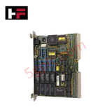
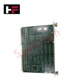
Product Details
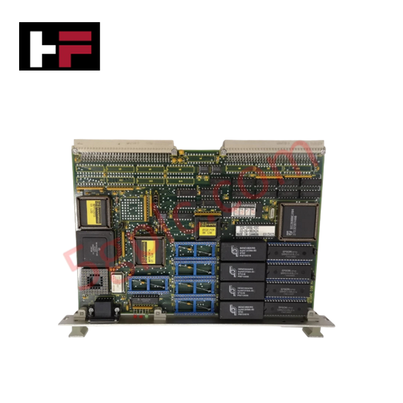
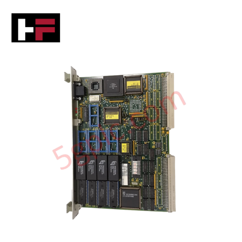
The GE WESDAC D20M++, also cataloged as the WESDAC D20M++ Control Module, operates as a dedicated hardware component for localized processing scaling and network medium conversion within WESDAC D20 system architectures.
Hardware Specifications
| Parameter | Specification |
|---|---|
| Model | WESDAC D20M++ |
| Brand | GE Fanuc |
| Origin | United States |
| Weight | Standard VME Module Weight Profile |
| Dimensions | Standard VME Card Cage Form Factor |
| Operating Temp | -20 - +60 deg C |
| Power Consumption | Backplane Dependent |
| Processor | High-performance microprocessor optimized for industrial control |
| Platform Interface | VMEbus Standard |
| RAM Layout | Volatile program execution registers |
| ROM Layout | Non-volatile operating system and application storage |
Suffix Breakdown & Model Matrix
- WESDAC D20M: Base system processing architecture designator establishing the VMEbus control backbone.
- ++: Performance extension designator indicating upgraded micro-processing capabilities and enhanced board-level memory capacity scaling boundaries over previous product revisions.
Profinet / EtherNet/IP Deterministic Networks and Firmware Flash Compatibility
The micro-processing platform interfaces directly across the high-speed VMEbus backplane path to organize memory boundaries and register maps. To secure deterministic response windows and avoid frame sequencing crashes when translating automated telemetry packets to adjacent sub-station segments or Profinet / EtherNet/IP deterministic networks, all interconnected nodes must match specific base configuration layers. Operating system files and logic applications housed in the non-volatile ROM rely on matching verified firmware flash compatibility baselines to prevent slot addressing errors.
Frequently Asked Questions
Q: Does the WESDAC D20M++ module support physical extraction while the VME chassis is powered?
A: No. The backplane design conforms to standard VMEbus mechanical layouts without staggered pre-charge power lines. Pulling or inserting the processor while power rails are live can cause electrical latch-up, destroying local logic components and interrupting active data traffic.
Q: How is memory alignment verified during a replacement of the processor node?
A: The configuration workspace maps program variables directly to the hardware boundaries. The replacement module must be audited via the configuration environment to verify that its physical layout and firmware flash compatibility registers correspond precisely to the master node structure.
Field Installation Guidelines
- Backplane Insertion Method: Slide the VME card uniformly along the plastic sub-rack guide channels, applying even horizontal force until the male interface pins fully engage the passive backplane sockets.
- Faceplate Screw Torque: Fully tighten the upper and lower faceplate retention screws into the chassis framework to establish continuous chassis grounding and isolate the module from physical vibration.
- Fiber and Copper Routing: Maintain physical separation between high-speed communication lines and parallel power cables inside the enclosure panel to mitigate high-frequency electromagnetic noise induction across the internal processor core.
Additional Information
- 100% Genuine Parts: All products are original and authentic, ensuring reliable industrial performance.
- 30-Day Refund Guarantee: Return any in-stock item within 30 days in original, unopened packaging for a full refund (excluding shipping and fees).
- 12-Month Warranty: Covers defects in materials or workmanship; excludes misuse, normal wear, or unauthorized modifications.
- Worldwide Shipping: We ship via USPS, UPS, FedEx, and DHL. Delivery times vary by country and may be subject to customs or import fees.
- Support & Contact: Technical and warranty assistance is available anytime. Contact us here: Contact.
- Purchase Guidance: Check product specifications and compatibility carefully before ordering to ensure proper application.


Tech & Buying Guide

Demystifying the DDE Protocol in Legacy Industrial Automation Systems
Modern control systems rely heavily on seamless interprocess communication to exchange operational data between software programs. Microsoft first introduced the Dynamic Data Exchange (DDE) protocol in 1987 to enable real-time data sharing. In factory automation, DDE served as an early bridge between control software and Windows desktop applications. Therefore, understanding DDE mechanics provides crucial insights into how legacy industrial networks established software-level connectivity.

Demystifying CPU Communication Ports in Siemens PLC Architectures
Industrial automation relies heavily on robust data exchange between devices. Without seamless connectivity, field instruments, network switches, human-machine interfaces, and programmable logic controllers cannot coordinate effectively. Therefore, understanding the various CPU communication ports available in Siemens hardware ensures efficient factory automation design and seamless system integration.

Mastering the Siemens PLC Scan Cycle: How the CPU Executes Automation Programs
Industrial automation relies heavily on programmable logic controllers (PLCs) to manage complex manufacturing processes. Many engineers dive straight into programming without mastering the underlying architecture. However, understanding how a PLC CPU executes a program ensures reliable system design. Therefore, mastering the scan cycle optimizes both performance and troubleshooting in modern control systems.