










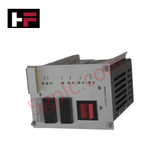
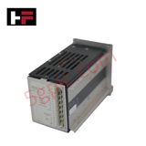
Product Details
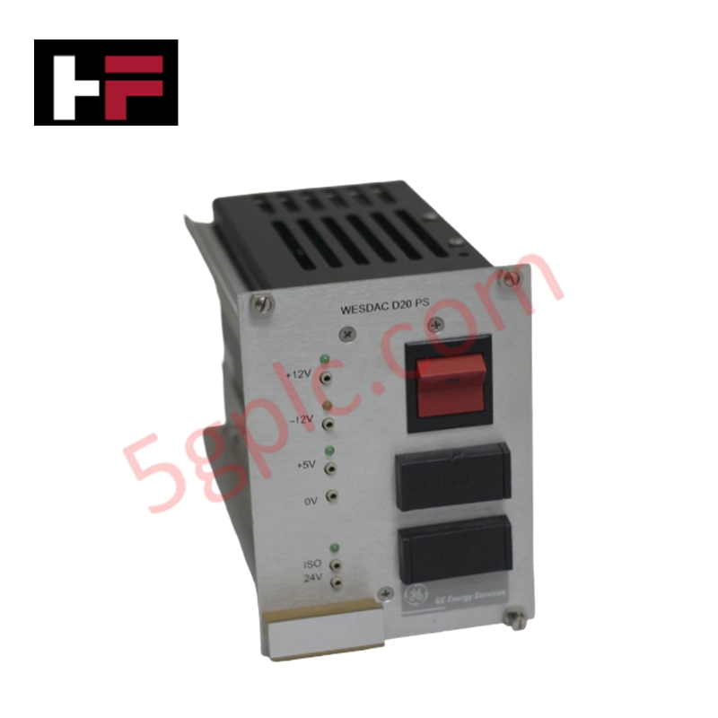
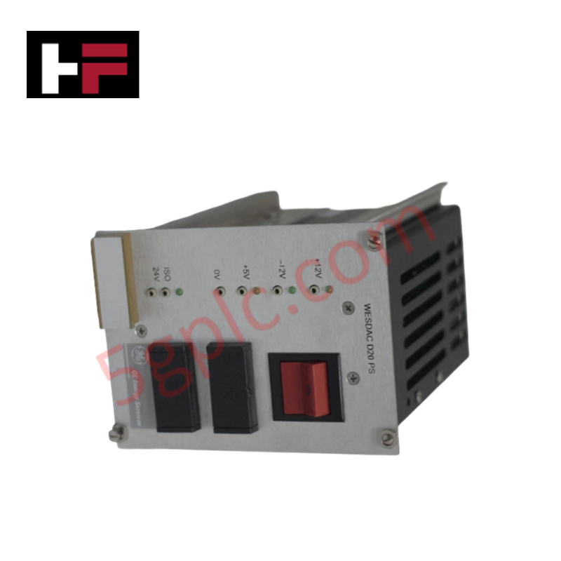
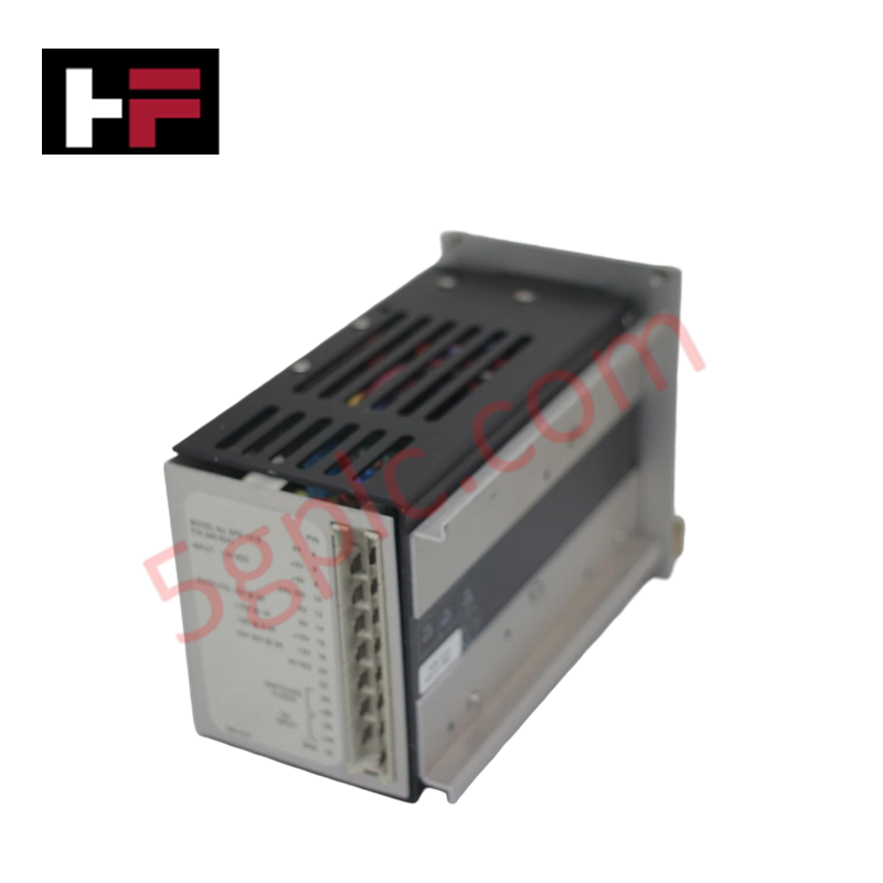
Configured for discrete status signal acquisition and logic level verification in WESDAC distributed sub-stations, the GE WESDAC D20 PS (WESDAC D20 PS Status Input Module) provides direct physical/electrical execution.
Hardware Specifications
| Parameter | Specification |
|---|---|
| Model | WESDAC D20 PS |
| Brand | GE (General Electric) |
| Origin | United States |
| Weight | Standard D20 Series Peripheral Weight Profile |
| Dimensions | Compact Substation Rack Chassis Enclosure |
| Operating Temp | -20 - +60 deg C |
| Power Consumption | Base Supply Input: 24 VDC +/- 10% |
| Input Channel Isolation | Channel-to-Backplane Opto-Coupled Isolation |
| Communication Interfaces | Modbus RTU, Modbus TCP/IP, EtherNet/IP |
| Configuration Tool | GE Logic Developer Software Environment |
| Local Visual Interface | Integrated LCD Status Panel Display |
| Electrical Protection | Overvoltage, overcurrent, short-circuit protection |
| Power Quality Filters | Onboard power factor correction and harmonic filtering |
Profinet / EtherNet/IP Deterministic Networks and I/O Density Scaling
The peripheral module processes binary state variables from field dry contacts and maps them directly into internal system status registers. When building complex remote terminal units, I/O density scaling relies on sequential backplane bus extension lines that run parallel communication protocols, such as EtherNet/IP deterministic networks or Modbus TCP/IP structures. To secure strict determinism during multi-point signal transitions, all data mapping definitions must align with verified firmware flash compatibility matrices running on the upstream D20 processor node.
Frequently Asked Questions
Q: Does the WESDAC D20 PS module support online hot-swapping during active backplane logic scanning?
A: No. The internal logic bus traces and the 24 VDC auxiliary power supply rails do not feature staggered pre-charge pin arrangements. Removing the module while the backplane is energized can generate voltage transients that interrupt active network traffic.
Q: How do the integrated harmonic filtering and power factor correction circuits handle voltage variations?
A: The onboard filtering components stabilize incoming power feeds within the 24 VDC +/- 10% voltage window. This hardware framework suppresses line-induced noise and electrical spikes before they reach the internal discrete isolation circuits.
Field Installation Guidelines
- Chassis Panel Grounding: Mount the module frame firmly onto the metallic backpanel rail, ensuring all fastening screws breach anodized surfaces to achieve a direct, low-impedance ground connection.
- Signal Wire Segregation: Route all discrete 24 VDC input lines through dedicated wireways separated from high-current AC power conductors to prevent capacitive noise coupling across data lines.
- Network Shield Continuity: Terminate the communication cable shields at a single point near the enclosure entry gland to block external electromagnetic field interference.
Additional Information
- 100% Genuine Parts: All products are original and authentic, ensuring reliable industrial performance.
- 30-Day Refund Guarantee: Return any in-stock item within 30 days in original, unopened packaging for a full refund (excluding shipping and fees).
- 12-Month Warranty: Covers defects in materials or workmanship; excludes misuse, normal wear, or unauthorized modifications.
- Worldwide Shipping: We ship via USPS, UPS, FedEx, and DHL. Delivery times vary by country and may be subject to customs or import fees.
- Support & Contact: Technical and warranty assistance is available anytime. Contact us here: Contact.
- Purchase Guidance: Check product specifications and compatibility carefully before ordering to ensure proper application.


Tech & Buying Guide

How to Connect to Siemens S7 PLCs: 5 Essential Communication Methods
Establishing a reliable hardware link between a programming terminal and a Siemens SIMATIC controller is essential for engineering workflows. Field engineers rely on distinct physical layers, ranging from legacy serial connections to high-speed Industrial Ethernet protocols. Modern factory automation environments prioritize fast data transfer and seamless driver integration. Selecting the correct connection method simplifies program downloads, online monitoring, and system troubleshooting in complex control systems.

Will PLCs Become Obsolete? The Future of Control Systems in Industry 4.0
Modern manufacturing is undergoing a rapid technological transformation driven by Industry 4.0 innovations. Technologies like Artificial Intelligence (AI), Machine Learning (ML), and the Industrial Internet of Things (IIoT) are dominating discussions across the factory automation sector. Consequently, many engineers wonder if these advanced digital tools will eventually replace traditional Programmable Logic Controllers (PLCs). However, evaluating the core physics of industrial operations reveals a very different reality for control systems.

Demystifying Open Platform Communication (OPC): The Backbone of Industrial Interoperability
Interoperability remains a cornerstone requirement for modern smart factories and process automation. Open Platform Communication (OPC) bridges the gap between disparate hardware platforms, control systems, and visualization software. By establishing a universal communication standard, OPC allows field controllers, SCADA platforms, and enterprise software from different vendors to exchange real-time data seamlessly.