


Product Details
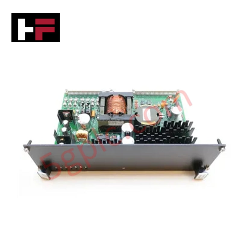
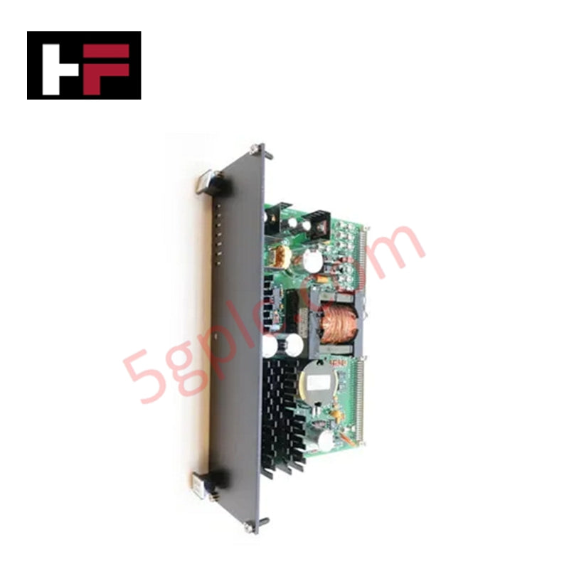
Configured for power conversion in EX2100 excitation control systems, the GE IS200EPSMG1A (IS200EPSMG1A Exciter Power Supply Module) provides direct physical/electrical execution of DC-to-DC voltage regulation and distribution.
Hardware Specifications
| Parameter | Specification |
|---|---|
| Model | IS200EPSMG1A |
| Brand | General Electric |
| Origin | USA |
| Input Voltage | 125 V DC |
| Output Rails | +5 V DC, +15 V DC, +24 V DC, Isolated +70 V DC |
Profinet / EtherNet/IP Deterministic Networks
The IS200EPSMG1A module utilizes a dual-stage power architecture consisting of a buck-regulator and a push-pull inverter. The buck-regulator steps down the primary 125 V DC input to an intermediate 50 V DC rail, which is subsequently processed by the push-pull inverter to generate the system-required multi-voltage outputs. This design ensures high-voltage galvanic isolation between the input source and the control backplane. The module supports deterministic system stability by maintaining precise voltage regulation on the +5 V DC, +15 V DC, and +24 V DC rails, which are distributed via the Exciter Power Backplane (EPBP). The firmware flash compatibility and logic-level monitoring facilitate I/O density scaling by ensuring stable power delivery to peripheral modules, including fans, crowbar circuits, and field current instrumentation.
Frequently Asked Questions
Q: Can the EPSMG1 be interchanged with the EPSMG2?
A: No. The EPSMG1 is strictly designated for use in excitation control system cabinets (powered by the EPBP backplane), whereas the EPSMG2 is utilized for regulator control and includes mounting provisions for the EPSD daughterboard.
Q: How is the contact wetting voltage generated?
A: The module provides an isolated +70 V DC output rail specifically dedicated to terminal board contact wetting, ensuring electrical separation from the logic-level power circuits.
Field Installation Guidelines
- Backplane Mounting: Ensure the IS200EPSMG1A is installed into the EPBP Exciter Power Backplane located beneath the EBKP backplane. Verify that connectors P1 and P2 are fully seated to ensure secure power distribution.
- Input Voltage Verification: Confirm the primary 125 V DC input source from the Power Distribution Module (PDM) is within nominal parameters before engagement to avoid overstressing the buck-regulator stage.
- Thermal Management: Maintain clear airflow around the module mounting position. Although the push-pull inverter is efficient, thermal dissipation is required to ensure long-term stability of the internal power semiconductors.
- Output Loading: When connecting external 24 V DC peripherals (e.g., fans, ground detectors), ensure the total current draw does not exceed the rated output capacity of the module to prevent premature protection triggering.
Additional Information
- 100% Genuine Parts: All products are original and authentic, ensuring reliable industrial performance.
- 30-Day Refund Guarantee: Return any in-stock item within 30 days in original, unopened packaging for a full refund (excluding shipping and fees).
- 12-Month Warranty: Covers defects in materials or workmanship; excludes misuse, normal wear, or unauthorized modifications.
- Worldwide Shipping: We ship via USPS, UPS, FedEx, and DHL. Delivery times vary by country and may be subject to customs or import fees.
- Support & Contact: Technical and warranty assistance is available anytime. Contact us here: Contact.
- Purchase Guidance: Check product specifications and compatibility carefully before ordering to ensure proper application.


Tech & Buying Guide

Navigating Industrial Automation Failures: Types, Causes, and Mitigation Strategies
Modern manufacturing relies heavily on automated control systems to maximize throughput and maintain product quality. However, unplanned downtime in industrial automation can cost facility operators thousands of dollars per hour. Understanding how programmable logic controllers (PLCs), distributed control systems (DCS), and field instrumentation fail empowers engineering teams to implement robust preventive maintenance strategies.

Essential Motion Control Commands: A Practical Guide for Engineers
Automation engineers often rely on precise position and speed control to drive modern factory machinery. Modern industrial systems, such as Programmable Logic Controllers (PLCs) and Distributed Control Systems (DCS), depend heavily on standardized motion instructions. Mastering these commands ensures operational safety, protects mechanical components, and optimizes cycle times across production lines.

The Role of Intrinsic Safety Barriers in PLC and DCS Architectures
Implementing robust protection in hazardous industrial environments represents a fundamental safety requirement in factory automation. Process facilities often handle volatile gases, dusts, and chemical agents that pose significant combustion risks. Consequently, control system engineers must deploy energy-limiting interfaces to isolate safe-area control cabinets from hazardous-area field instrumentation. This article examines the function, selection, and electrical principles of intrinsic safety barriers within modern PLC and DCS networks.