










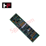
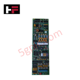
Product Details
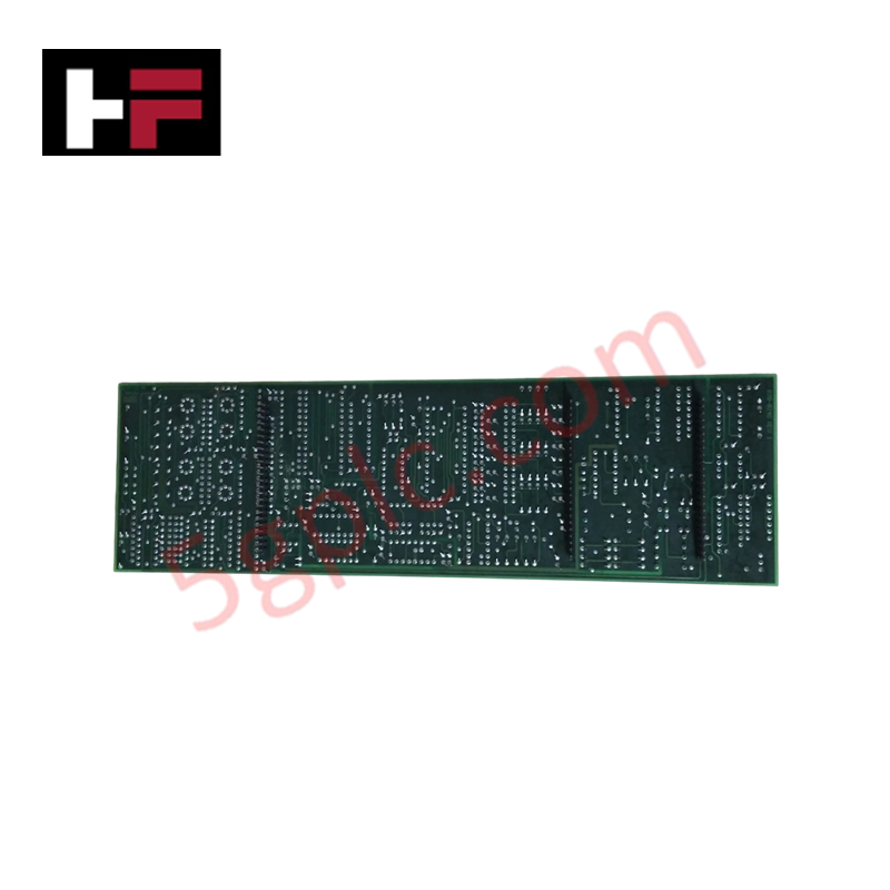
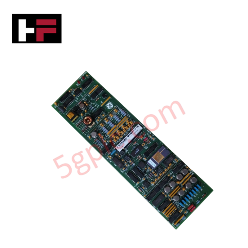
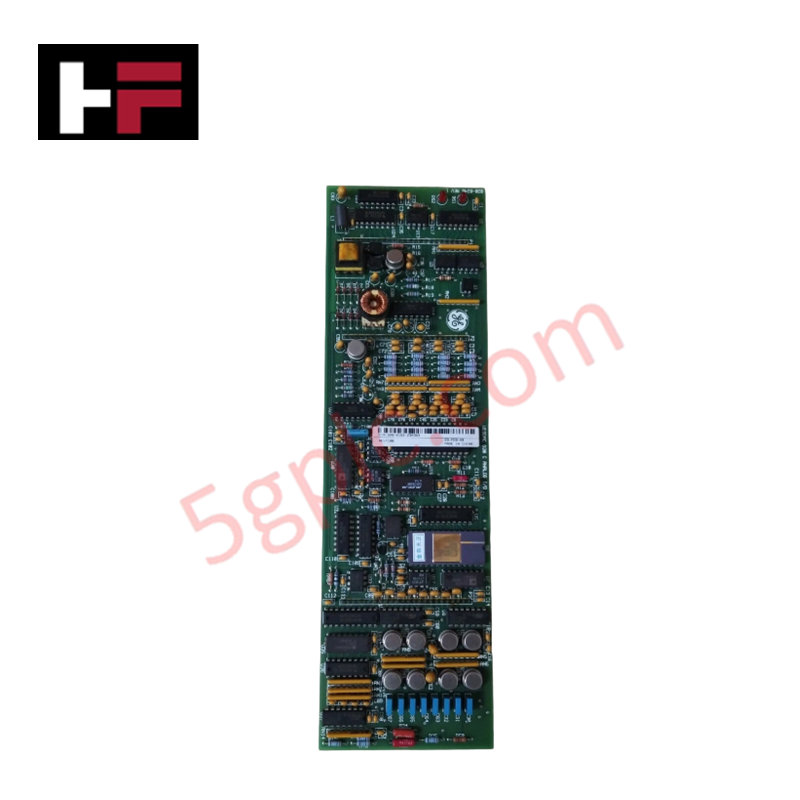
Configured for analog data acquisition and discrete relay control execution in electrical substation automation platforms, the GE WESDAC D20 C (GE D20C Analog Digital I/O Module) provides direct physical/electrical execution. The hardware integrates localized multi-channel monitoring and command-relay routing within a single distributed architecture node, maintaining deterministic processing intervals across all configured internal circuits.
Hardware Specifications
| Parameter | Specification |
|---|---|
| Model | WESDAC D20 C (D20C) |
| Brand | GE (General Electric) |
| Origin | United States |
| Weight | 2.5 kg (Approximate based on physical frame assembly) |
| Dimensions | 19.0" x 5.25" x 2.5" (Standard 19-inch rackmount width) |
| Operating Temp | -20 to +70 deg C (Standard industrial substation rating) |
| Power Consumption | 5 W typical (20-60 VDC range), 11 W maximum with 24 VDC contact wetting active |
| Processor Type | 8-bit Freescale 68HC11 MPU |
| Clock Speed | 2 MHz MPU clock |
| Onboard Memory | 24 KB EPROM, 32 KB static RAM, 512 bytes EEPROM |
| Analog Inputs | 16 bipolar, differential inputs via plug-in daughter board |
| Analog Accuracy | +/-0.05% for voltage configurations, +/-0.1% for current configurations |
| Temperature Drift | +/-10 ppm per deg C |
| ADC Resolution | 14 bits plus sign bit |
| Scan Conversion Rate | 275 ms for 16 inputs @ 60 Hz line filter, 328 ms for 16 inputs @ 50 Hz line filter |
| Dynamic Input Range | 125% of normalized full-scale inputs |
| Control Outputs | 8 interposing relays plus 2 Master Trip/Close relays, or 8 isolated Form C contacts |
| Contact Switching Rating | 60 W maximum, 3 A maximum, 220 VDC maximum (single Form-C or -A contact) |
| Output Duration Control | Programmable 1 to 215 ms (1 ms intervals) or 1 to 215 s (1 s intervals) |
| Coil Integrity Check | Continuous status loop verification executed every 500 microseconds |
| Input Isolation Rating | 1500 Vrms component isolation, 1000 VDC dielectric rating |
| Network Communication | 2 dedicated D.20 Link ports, 1 local RS-232 maintenance port at 9600 baud |
| Local Interface | Physical toggle switch for local enable/disable authorization |
Industrial Control & Firmware Flash Compatibility
The architectural interface relies on low-latency backplane bus execution profiles synchronized directly with the Freescale MPU pipeline. Field deployment requires absolute verification of firmware flash compatibility versions when linking the sub-assembly to the primary D20 processor node. Operating parameters dictate that EEPROM allocation memory must match the system image map to preserve local calibration curves during hot-swap recovery cycles. If firmware revisions deviate from the core processing unit base level, communications across the dual D.20 Link ports will drop packets, triggering a hardware-driven local lockout state.
Frequently Asked Questions
Q: How does the local enable/disable switch alter the physical command state of the control relays?
A: The physical toggle switch acts as a hardware-level interlock that isolates the drive coils of the 8 control relays and the 2 Master Trip/Close relays from the internal logic. When toggled to the disable position, it prevents all remote execution commands from activating the output circuits, providing an absolute safety break for local physical maintenance.
Q: What is the mechanical and electrical isolation threshold between the analog processing electronics and the field wiring terminations?
A: The module incorporates optocouplers and magnetic transformers providing a component isolation rating of 1500 Vrms and a dielectric breakdown limit of 1000 VDC. This prevents high-voltage transient surges originating on external 4-20 mA or voltage loops from cross-propagating into the internal 8-bit MPU logic bus.
Q: How does the hardware handle scanning cycles if the grid frequency fluctuates between 50 Hz and 60 Hz?
A: The analog-to-digital converter relies on fixed hardware integration filters tailored to the line frequency. If configured for 60 Hz, the execution time for all 16 differential channels requires exactly 275 ms; if configured for 50 Hz, the integration window expands to 328 ms to suppress ambient line noise. Discrepancies between physical frequency and software filter settings degrade accuracy margins beyond the stated specifications.
Field Installation Guidelines
- Rack Mounting & Thermal Dissipation: The unit must be secured within a standard 19-inch electronic enclosure using high-tensile machine screws. Maintain a minimum of 1U (44.45 mm) structural clearance above and below the assembly frame to permit unrestricted natural convection cooling across the internal daughterboard heat sinks.
- Field Wiring and Shielding Terminations: All analog differential signals must be routed using twisted-pair cables with overall braided foil shields. Ground all shield tails exclusively at the master substation terminal ground busbar; do not daisy-chain shields or ground them at both ends to eliminate ground loop current injection into the 14-bit ADC stage.
- Relay Contact Arc Suppression: For inductive DC loads connected to the Form C output relays, external flyback diodes must be reverse-biased across the external load terminal points. Failure to deploy suppression will induce high-voltage arcing during contact break sequences, accelerating mechanical pitting and degrading the 60 W maximum switching limit.
- Power Input Grounding: The 20-60 VDC primary power supply lines must be routed through a dedicated circuit breaker. Connect the chassis ground terminal directly to the panel frame using a low-impedance copper conductor with a minimum cross-sectional area of 2.5 mm squared.
Additional Information
- 100% Genuine Parts: All products are original and authentic, ensuring reliable industrial performance.
- 30-Day Refund Guarantee: Return any in-stock item within 30 days in original, unopened packaging for a full refund (excluding shipping and fees).
- 12-Month Warranty: Covers defects in materials or workmanship; excludes misuse, normal wear, or unauthorized modifications.
- Worldwide Shipping: We ship via USPS, UPS, FedEx, and DHL. Delivery times vary by country and may be subject to customs or import fees.
- Support & Contact: Technical and warranty assistance is available anytime. Contact us here: Contact.
- Purchase Guidance: Check product specifications and compatibility carefully before ordering to ensure proper application.


Tech & Buying Guide

Comprehensive Guide to PLC Types in Modern Industrial Automation
Modern industrial automation relies on programmable logic controllers to govern critical factory operations. System integrators classify PLCs based on scale, hardware architecture, and power supply design. Understanding these core categories enables automation engineers to select the right control system architecture. Consequently, proper hardware selection optimizes performance while minimizing long-term operational costs.

Demystifying the DDE Protocol in Legacy Industrial Automation Systems
Modern control systems rely heavily on seamless interprocess communication to exchange operational data between software programs. Microsoft first introduced the Dynamic Data Exchange (DDE) protocol in 1987 to enable real-time data sharing. In factory automation, DDE served as an early bridge between control software and Windows desktop applications. Therefore, understanding DDE mechanics provides crucial insights into how legacy industrial networks established software-level connectivity.

Demystifying CPU Communication Ports in Siemens PLC Architectures
Industrial automation relies heavily on robust data exchange between devices. Without seamless connectivity, field instruments, network switches, human-machine interfaces, and programmable logic controllers cannot coordinate effectively. Therefore, understanding the various CPU communication ports available in Siemens hardware ensures efficient factory automation design and seamless system integration.