


Product Details
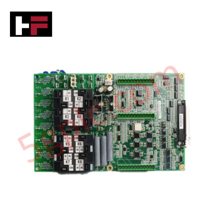
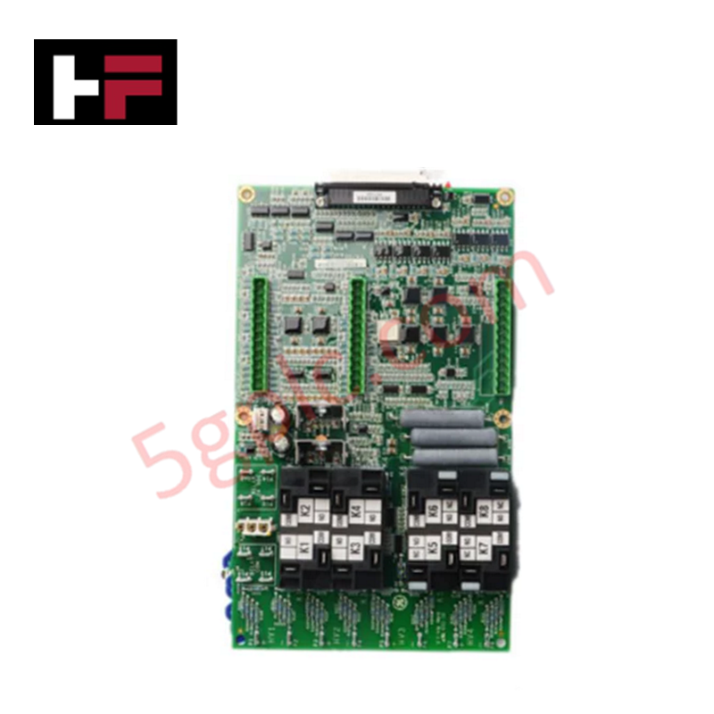
Configured for signal regulation and control logic in Mark V Speedtronic systems, the GE IS210AEAAH1BJE (IS210AEAAH1BJE Printed Circuit Board) provides direct physical and electrical execution of analog signal processing and I/O interface management.
Hardware Specifications
| Parameter | Specification |
|---|---|
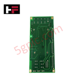
| Model | IS210AEAAH1BJE |
| Brand | General Electric |
| Origin | USA |
| Weight | 1.10 kg |
| Dimensions | 812 x 516 x 825 mm |
| Operating Temp | Industrial rated range |
| Power Consumption | 24 VDC |
| Input Voltage | 24 VDC |
| Output Voltage | 0-10 VDC |
| Maximum Current | 2 A |
Backplane Bus Communication Velocity Licences
The IS210AEAAH1BJE functions within the Mark V control architecture as a modular interface unit capable of managing both digital and analog signal streams. The board supports high-speed processing cycles, allowing the system to execute control tasks with minimal latency. Firmware flash compatibility is dictated by the legacy Mark V platform requirements, requiring correct revision alignment during field integration. The architecture supports I/O density scaling through modular expansion, enabling the connection of diverse sensor types and special-purpose signals. Deterministic network performance is maintained by standardized backplane bus communication, ensuring that data packets are processed consistently across the controller bus without collision or timing degradation.
Frequently Asked Questions
Q: Is this board compatible with modern Mark VIe communication protocols?
A: No. The IS210AEAAH1BJE is specifically engineered for the Mark V Speedtronic platform and utilizes legacy bus communication standards. It is not directly compatible with Mark VIe Ethernet-based IONet.
Q: What are the primary considerations for replacing this PCB in an existing chassis?
A: Ensure that the system is de-energized before extraction to prevent backplane short circuits. Verify that the hardware revision (AEAA) matches the existing system documentation to ensure firmware compatibility and pinout alignment.
Field Installation Guidelines
- Mounting: Carefully insert the board into the designated Mark V controller slot. Ensure the board guides are aligned correctly to prevent damage to the backplane connector pins.
- Wiring: Secure all field signal terminations at the terminal block. Ensure that the 24 VDC power input is verified with a multimeter before closing the circuit to avoid overvoltage damage to the analog outputs.
- Shielding: Route all signal cabling through grounded conduits. Keep 0-10 VDC analog signal wires separated from high-voltage AC cabling to prevent induced noise and signal oscillation.
- Integration: Once installed, monitor the control system diagnostics to verify that the module is communicating with the main processor. Perform a signal calibration for the 0-10 VDC output to ensure loop accuracy.
- Thermal Management: Ensure the cabinet cooling fans are operational. The board is designed for industrial environments, but stable airflow is necessary to maintain the long-term integrity of the surface-mount components.
Additional Information
- 100% Genuine Parts: All products are original and authentic, ensuring reliable industrial performance.
- 30-Day Refund Guarantee: Return any in-stock item within 30 days in original, unopened packaging for a full refund (excluding shipping and fees).
- 12-Month Warranty: Covers defects in materials or workmanship; excludes misuse, normal wear, or unauthorized modifications.
- Worldwide Shipping: We ship via USPS, UPS, FedEx, and DHL. Delivery times vary by country and may be subject to customs or import fees.
- Support & Contact: Technical and warranty assistance is available anytime. Contact us here: Contact.
- Purchase Guidance: Check product specifications and compatibility carefully before ordering to ensure proper application.


Tech & Buying Guide

Navigating Industrial Automation Failures: Types, Causes, and Mitigation Strategies
Modern manufacturing relies heavily on automated control systems to maximize throughput and maintain product quality. However, unplanned downtime in industrial automation can cost facility operators thousands of dollars per hour. Understanding how programmable logic controllers (PLCs), distributed control systems (DCS), and field instrumentation fail empowers engineering teams to implement robust preventive maintenance strategies.

Essential Motion Control Commands: A Practical Guide for Engineers
Automation engineers often rely on precise position and speed control to drive modern factory machinery. Modern industrial systems, such as Programmable Logic Controllers (PLCs) and Distributed Control Systems (DCS), depend heavily on standardized motion instructions. Mastering these commands ensures operational safety, protects mechanical components, and optimizes cycle times across production lines.

The Role of Intrinsic Safety Barriers in PLC and DCS Architectures
Implementing robust protection in hazardous industrial environments represents a fundamental safety requirement in factory automation. Process facilities often handle volatile gases, dusts, and chemical agents that pose significant combustion risks. Consequently, control system engineers must deploy energy-limiting interfaces to isolate safe-area control cabinets from hazardous-area field instrumentation. This article examines the function, selection, and electrical principles of intrinsic safety barriers within modern PLC and DCS networks.