Essential Best Practices for PLC Wiring and Installation in Industrial Automation
- 〡
- 〡 by WUPAMBO

Navigating Manufacturer Specifications and Power Wiring Standards
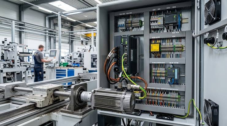
Successful control system deployment begins with thoroughly reviewing manufacturer technical documentation. Controllers from major brands like Allen-Bradley, Siemens, and Schneider Electric feature unique terminal layouts. Engineers must verify voltage requirements before connecting power cables to prevent catastrophic equipment damage. Standard line connections require strict adherence to regional electrical codes and proper wire color coding. Furthermore, panel builders should always establish a robust low-impedance ground connection using at least 16-AWG copper conductor tied directly to the main plant grounding grid.
Configuring Discrete Input Cards: Sinking versus Sourcing Circuits
Proper input field device wiring guarantees accurate signal acquisition in factory automation systems. Technicians must understand sinking and sourcing configurations to ensure reliable discrete sensor operation. Sinking inputs connect the common terminal to the positive power rail, whereas sourcing inputs connect common to the negative terminal. Operators land individual discrete field wires from pushbuttons or limit switches onto assigned input terminals such as I:0/0. Modern industrial automation projects increasingly favor 24 VDC input circuits over high-voltage AC lines because lower voltages enhance maintenance personnel safety.
Implementing Secure Output Card Wiring and Circuit Protection
Actuator signal lines require dedicated overload and short-circuit protection to safeguard output modules. Engineers must install fast-acting fuses for high-risk field loads like solenoid valves and hydraulic actuators. Inductive switching spikes regularly generate back electromotive force (EMF), which degrades solid-state and relay outputs over time. Therefore, maintenance teams must install metal oxide varistors (MOVs) or RC snubbers across AC loads. Similarly, flyback diodes across DC solenoids effectively suppress harmful transient voltage spikes.
Mitigating Noise Interference and Optimizing Control Panel Layout
Electromagnetic interference (EMI) degrades sensor signal integrity and causes random control system faults. Panel assembly crews must maintain physical separation between high-voltage AC cables and sensitive 24 VDC signal lines. In addition, instrument engineers must specify twisted-pair, shielded cabling for analog sensors to block ambient electrical noise. Technicians must install clear, machine-printed heat-shrink wire sleeves on every conductor because handwritten labels degrade over time and complicate troubleshooting procedures.
Practical Application Scenario: Chemical Processing Plant Panel Overhaul
During a recent control panel retrofitting project at a chemical manufacturing plant, field engineers corrected severe intermittent sensor dropouts caused by poor initial cabling design. The team isolated high-power motor leads into separate cable trays, away from sensitive analog instrument loops. Furthermore, adding flyback suppression diodes across all 24 VDC inductive valve coils eliminated recurring output module channel failures. Implementing printed heat-shrink wire sleeve labels reduced subsequent routine maintenance diagnostic time by over 40 percent.
About the Author
Zhang Minghui is a Senior Control Systems Consultant with 15 years of global hands-on experience specializing in PLC hardware architecture, DCS integration, TSI monitoring, and power protection design. He regularly publishes technical white papers and practical engineering guides to help B2B industrial automation professionals optimize panel build quality and operational uptime.
- Posted in:
- cabinet wiring
- control systems
- DCS
- factory automation
- I/O modules
- PLC wiring
- surge suppression