


Product Details
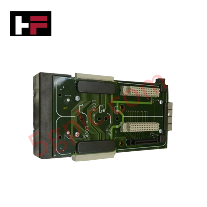
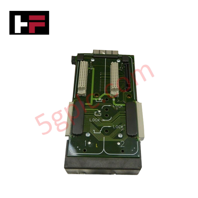
Configured for module integration in DeltaV control architectures, the Emerson VE3051C0 (VE3051C0 2-Wide Power/Controller Carrier) provides direct physical/electrical execution of power distribution and backplane communication for controller assemblies.
Hardware Specifications
| Parameter | Specification |
| Model | VE3051C0 |
| Brand | Emerson |
| Origin | USA |
| Weight | 0.73 kg (1.61 lbs) |
| Dimensions | 2-wide slot width |
| Operating Temp | Not specified |
| Power Consumption | Passive power distribution |
| Input Voltage | 30 VDC |
| Current Rating | 8 A |
Process Control: Channel-to-Channel Isolation
The VE3051C0 carrier provides the foundational backplane structure for the M-Series controller ecosystem. It incorporates channel-to-channel isolation paths that isolate the controller's internal control logic from the field power input bus. By separating the 30 VDC power distribution plane from the backplane communication pins, the carrier minimizes the risk of signal crosstalk and electrical noise interference. This isolation is maintained during the mounting of the power supply and the MQ controller modules, ensuring that transient disturbances at the power entry point are decoupled from the controller backplane bus.
Frequently Asked Questions (FAQ)
Q: Can the power input be wired redundantly on this carrier?
A: The VE3051C0 is designed to facilitate power input from the system power supply. Redundant power configurations must be handled via the external power supply modules connected to the carrier's power input terminals; the carrier itself handles the distribution of this power across its internal bus.
Q: What is the maximum load this carrier can support?
A: The carrier is rated for a continuous current of 8 A. Users must calculate the cumulative current draw of all mounted controller and power supply modules to ensure the total load does not exceed this rating, preventing thermal degradation of the carrier backplane traces.
Field Installation Guidelines
-
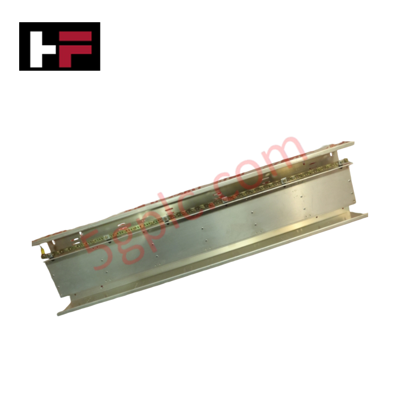
Mounting: Secure the carrier to the mounting plate using the integrated mounting holes. Ensure the surface is flat and the carrier is properly aligned to prevent mechanical stress on the backplane connectors.
-
Power Connections: Connect the 30 VDC supply to the designated power input terminals. Use copper conductors sized appropriately for the 8 A load and ensure all connections are torqued to specifications to prevent high-resistance contact points.
-
Grounding: Bond the carrier chassis to the system earth ground. This is required for electromagnetic compatibility and to ensure the effectiveness of the internal galvanic isolation barrier.
-
Module Seating: When inserting controllers or power modules, ensure the module keys align with the carrier slots. Apply firm, even pressure until the locking mechanism engages, verifying a solid connection with the backplane communication pins.
Additional Information
- 100% Genuine Parts: All products are original and authentic, ensuring reliable industrial performance.
- 30-Day Refund Guarantee: Return any in-stock item within 30 days in original, unopened packaging for a full refund (excluding shipping and fees).
- 12-Month Warranty: Covers defects in materials or workmanship; excludes misuse, normal wear, or unauthorized modifications.
- Worldwide Shipping: We ship via USPS, UPS, FedEx, and DHL. Delivery times vary by country and may be subject to customs or import fees.
- Support & Contact: Technical and warranty assistance is available anytime. Contact us here: Contact.
- Purchase Guidance: Check product specifications and compatibility carefully before ordering to ensure proper application.
Tech & Buying Guide

Essential Motion Control Commands: A Practical Guide for Engineers
Automation engineers often rely on precise position and speed control to drive modern factory machinery. Modern industrial systems, such as Programmable Logic Controllers (PLCs) and Distributed Control Systems (DCS), depend heavily on standardized motion instructions. Mastering these commands ensures operational safety, protects mechanical components, and optimizes cycle times across production lines.

The Role of Intrinsic Safety Barriers in PLC and DCS Architectures
Implementing robust protection in hazardous industrial environments represents a fundamental safety requirement in factory automation. Process facilities often handle volatile gases, dusts, and chemical agents that pose significant combustion risks. Consequently, control system engineers must deploy energy-limiting interfaces to isolate safe-area control cabinets from hazardous-area field instrumentation. This article examines the function, selection, and electrical principles of intrinsic safety barriers within modern PLC and DCS networks.

Architectural Selection and Scale Classification of PLC Systems in Industrial Automation
Selecting the correct control platform represents a foundational engineering decision in factory automation. System designers must carefully balance technical parameters against long-term operational requirements when implementing a Programmable Logic Controller (PLC). This article examines the critical evaluation metrics, physical scale classifications, and operational architectures of modern control systems.