Architectural Selection and Scale Classification of PLC Systems in Industrial Automation
- 〡
- 〡 by WUPAMBO

Selecting the correct control platform represents a foundational engineering decision in factory automation. System designers must carefully balance technical parameters against long-term operational requirements when implementing a Programmable Logic Controller (PLC). This article examines the critical evaluation metrics, physical scale classifications, and operational architectures of modern control systems.
Key Evaluation Metrics for Controller Selection
Selecting an industrial controller requires a systematic analysis of multiple physical and performance parameters. Engineers must evaluate the required input/output (I/O) channel density, CPU processing speeds, memory requirements, scan times, and cost.
The primary metric defining physical controller scale remains the total I/O count. Engineers must also analyze CPU scan rates to ensure that safety-critical interlocking loops or rapid processing tasks execute within exact timing limits. Moreover, physical space constraints often dictate whether a compact design with ribbon-cable expansions or a modular backplane chassis is more appropriate.
Classifying Controller Scales by I/O Density
Control systems scale from localized micro-units to large, plant-wide architectures based on their total I/O capacity:
- Nano PLCs: These units typically support fewer than 15 I/O channels, housing processing and interface circuitry within a single, space-saving casing.
- Micro PLCs: These systems provide between 20 and 32 I/O points, supporting basic discrete automation applications.
- Small PLCs: Offering a range of 32 to 128 I/O channels, these controllers manage isolated machine operations.
- Medium PLCs: These platforms bridge the gap between machinery control and larger process blocks, managing 64 to 1024 I/O points.
- Large PLCs: These high-density systems support 512 to 4096 I/O connections, processing complex analog and digital networks.
- Very Large PLCs: These massive systems manage over 5000 I/O channels, coordinating complex plant-wide networks.
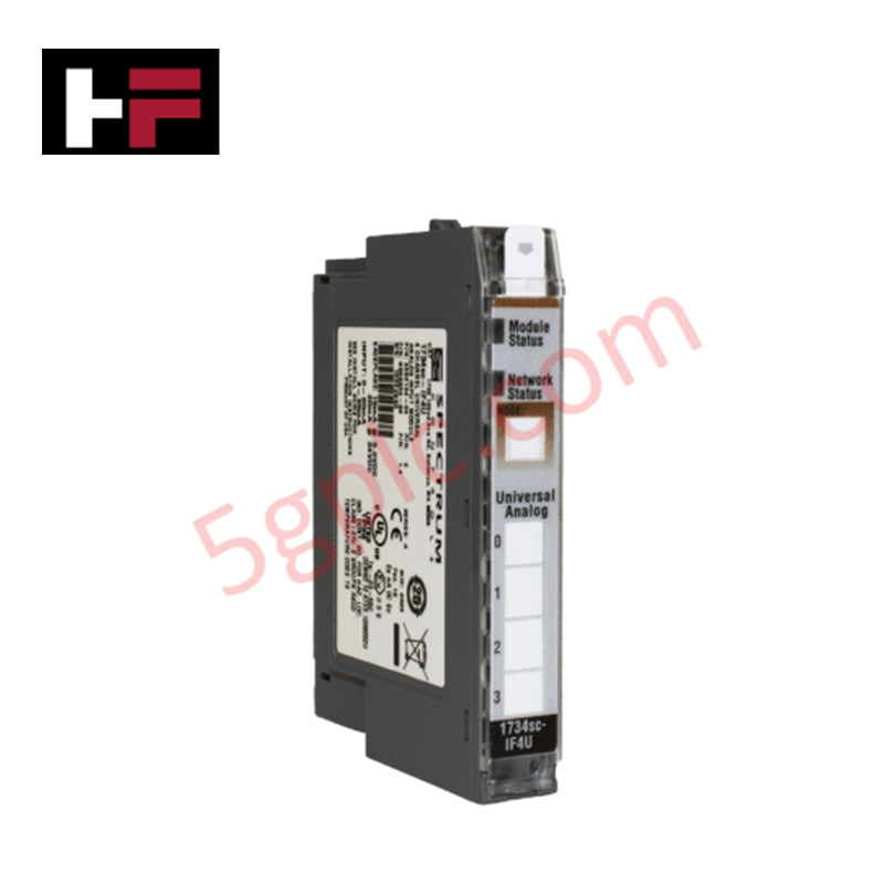
In modern industrial facilities, modular PLCs are the preferred choice. These systems allow engineers to add specialized I/O modules directly onto the active backplane to meet evolving application requirements.
Designing for Future I/O Capacity and Memory Overhead
Industrial control programs, physical I/O mapping tables, internal memory coils, and database libraries reside directly within the CPU memory. Consequently, engineers must accurately estimate their current and future memory usage during the system design phase.
A standard PLC memory word consists of 2 bytes, which is equivalent to 16 bits. Word length directly determines the data storage capacity of the PLC processor. For example, a CPU operating with an 8-bit word structure offers 49,152 bits of storage within a 6K memory block. In contrast, a 32-bit word architecture increases storage capacity to 196,608 bits within that same 6K memory envelope. As programmers add execution networks and physical hardware channels, the available memory overhead decreases. Experienced engineers typically leave a minimum of 20% to 30% spare memory and physical I/O capacity to accommodate future system expansions.
Structural Typologies of PLC Implementations
Modern industrial applications deploy PLC hardware in one of three primary structural configurations:
Standalone Implementations
This basic configuration utilizes a single, dedicated controller to execute all processing and localized logic. All field sensors and actuators wire directly back to this master unit. Standalone architectures are standard for isolated utility systems, such as air compressors or independent pump skids.
Multi-Task Implementations
Multi-task architectures distribute control functions across multiple interconnected PLCs. Each controller coordinates a specific process segment and shares operational parameters horizontally with peer nodes. Communication servers facilitate data exchange between the local controllers and supervisory computers.
Control Management Networks
This top-tier configuration integrates multiple localized PLCs with a central master processor. Local controllers execute time-critical logic and feed status updates to the master CPU. This hierarchical setup requires high-speed industrial networks like EtherNet/IP, Profinet, or Modbus TCP to handle rapid data transfer and supervisory control.
Real-World Application Scenario: Hybrid Processing Plant
Consider a municipal water filtration facility as a practical example of a multi-tier control management network. In this installation, several standalone Small and Medium PLCs manage local processes, such as chemical dosing, rapid sand filtration, and backwash pump sequencing.
These local units connect to a central Master PLC via a deterministic fiber-optic Ethernet network. The master PLC monitors plant-wide status, aggregates system alarms, and coordinates high-level water distribution, while local PLCs run their local interlocks independently. This distributed setup prevents a single point of failure from bringing down the entire plant.
About the Author: Chen Junjie
Chen Junjie is a senior industrial automation specialist with over 15 years of practical experience designing and commissioning PLC and DCS systems. He has engineered safety-critical and high-density control networks across the power generation, pulp and paper, and manufacturing sectors. Chen specializes in upgrading legacy control systems to modern Ethernet-based redundant architectures. He is a regular contributor of technical guides and hardware reviews to leading B2B automation media platforms.
- Posted in:
- Controller Memory
- I/O Density Scaling
- Modular PLC
- PLC Selection Criteria
- Programmable Logic Controllers