










Product Details
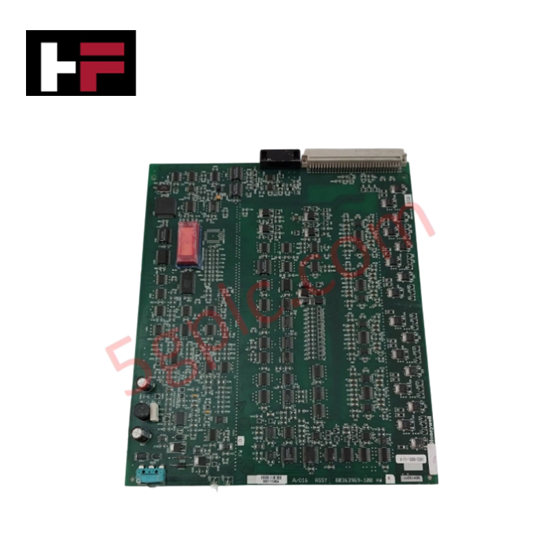
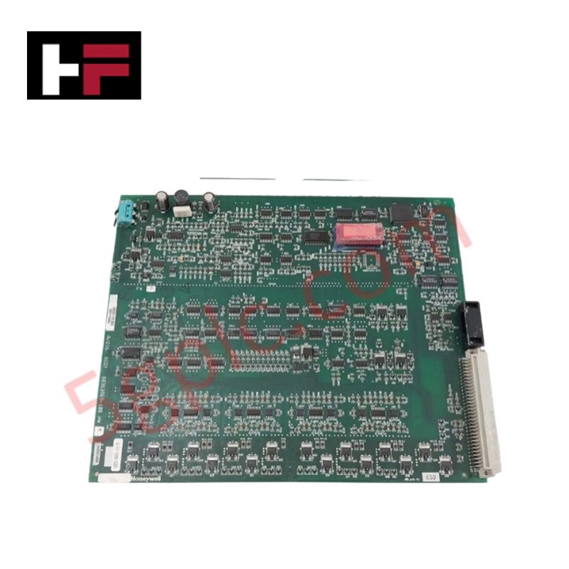
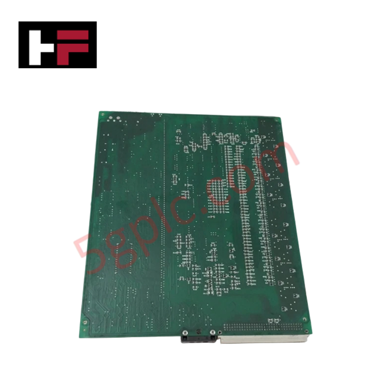
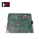
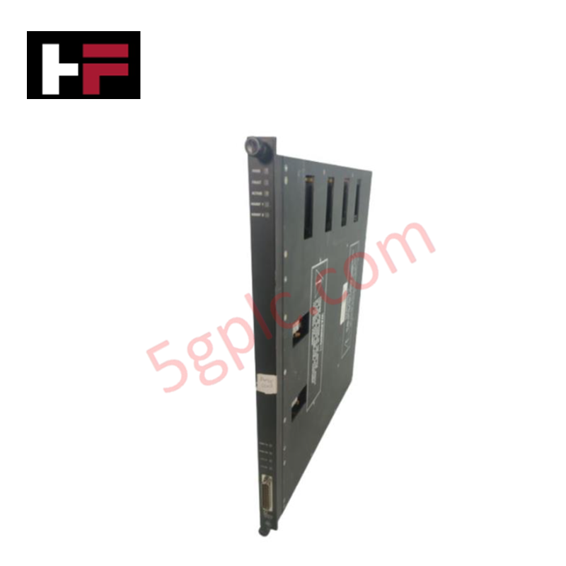
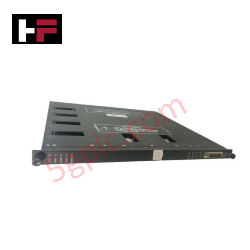
The Honeywell 80363969-100, also cataloged as the 80363969-100 Analog Output Processor Module, operates as a dedicated hardware component for converting digital control signals to analog outputs within Honeywell TDC 3000 and Process Manager architectures. It drives 16 isolated channels outputting 4-20 mA analog current directly to field positioning devices and analog control loops.
Hardware Specifications
| Parameter | Specification |
|---|---|
| Model | 80363969-100 |
| Brand | Honeywell |
| Origin | USA |
| Weight | 1.0 kg |
| Dimensions | 40 mm x 260 mm x 220 mm |
| Operating Temp | 0 deg C to 60 deg C |
| Power Consumption | Standard Backplane Load |
| Output Channels | 16 isolated channels |
| Output Range | 4-20 mA analog current |
| Compatible Terminal Boards | MU-TAOY22, MU-TAOY52, MC-TAOY22, MC-TAOY52 |
Channel-to-Channel Isolation and Loop Protocol Response
The Honeywell 80363969-100 incorporates internal optical decoupling across all 16 current loops to maintain channel-to-channel isolation. This galvanic barrier protects internal microprocessor logic against field ground loops and high-voltage electrical surges. When operating with 4-20 mA HART loop protocol field positioners, the digital-to-analog converter stage provides continuous loop impedance management to stabilize signal conversion over extended cable distances.
Frequently Asked Questions
Q: Are terminal connections made directly to the front face of the 80363969-100 module?
A: No. Field cabling connects to compatible external terminal assemblies such as the MU-TAOY22, MU-TAOY52, MC-TAOY22, or MC-TAOY52, which link to the module via dedicated multi-conductor cables.
Q: Can an individual 4-20 mA output channel be configured as a voltage output?
A: No. The internal digital-to-analog conversion circuitry is designed strictly for 4-20 mA current loop driving and does not provide native voltage output options.
Field Installation Guidelines
- Turn off main rack power and field loop power supplies prior to seating or removing the module from the chassis slot.
- Align the module circuit board with the chassis card guides and push firmly until the rear connectors seat securely into the backplane.
- Fasten the module retaining screws to ensure proper chassis grounding and mechanical retention under operational vibration.
- Route field signal cables through grounded, shielded conduits and separate them from high-voltage AC power wiring to prevent noise coupling.
- Verify that shield drain wires are tied to a single-point system ground block at the cabinet cable entrance.
Additional Information
- 100% Genuine Parts: All products are original and authentic, ensuring reliable industrial performance.
- 30-Day Refund Guarantee: Return any in-stock item within 30 days in original, unopened packaging for a full refund (excluding shipping and fees).
- 12-Month Warranty: Covers defects in materials or workmanship; excludes misuse, normal wear, or unauthorized modifications.
- Worldwide Shipping: We ship via USPS, UPS, FedEx, and DHL. Delivery times vary by country and may be subject to customs or import fees.
- Support & Contact: Technical and warranty assistance is available anytime. Contact us here: Contact.
- Purchase Guidance: Check product specifications and compatibility carefully before ordering to ensure proper application.


Tech & Buying Guide

Essential Best Practices for PLC Wiring and Installation in Industrial Automation
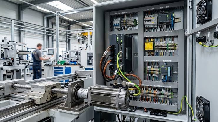
Successful control system deployment begins with thoroughly reviewing manufacturer technical documentation. Controllers from major brands like Allen-Bradley, Siemens, and Schneider Electric feature unique terminal layouts. Engineers must verify voltage requirements before connecting power cables to prevent catastrophic equipment damage. Standard line connections require strict adherence to regional electrical codes and proper wire color coding. Furthermore, panel builders should always establish a robust low-impedance ground connection using at least 16-AWG copper conductor tied directly to the main plant grounding grid.
Demystifying Programmable Logic Controllers: Comprehensive Guide to PLC Classification and Selection in Industrial Automation
Modern industrial automation heavily relies on Programmable Logic Controllers (PLCs) to drive factory floor efficiency. Over my 15 years as an industrial automation expert working with DCS, TSI, and control systems, I have seen PLCs evolve into the central nervous system of modern manufacturing. Selecting the right controller requires a deep understanding of PLC types based on physical size, hardware architecture, and power supply configurations.

Comprehensive Guide to PLC Types in Modern Industrial Automation
Modern industrial automation relies on programmable logic controllers to govern critical factory operations. System integrators classify PLCs based on scale, hardware architecture, and power supply design. Understanding these core categories enables automation engineers to select the right control system architecture. Consequently, proper hardware selection optimizes performance while minimizing long-term operational costs.