










Product Details
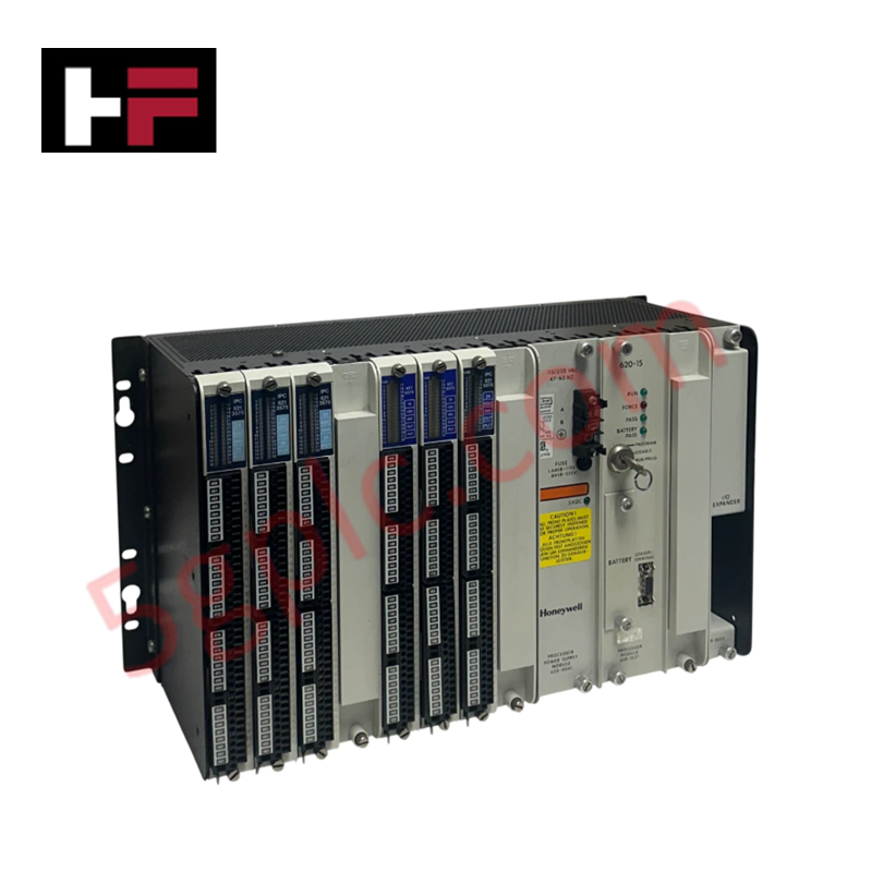
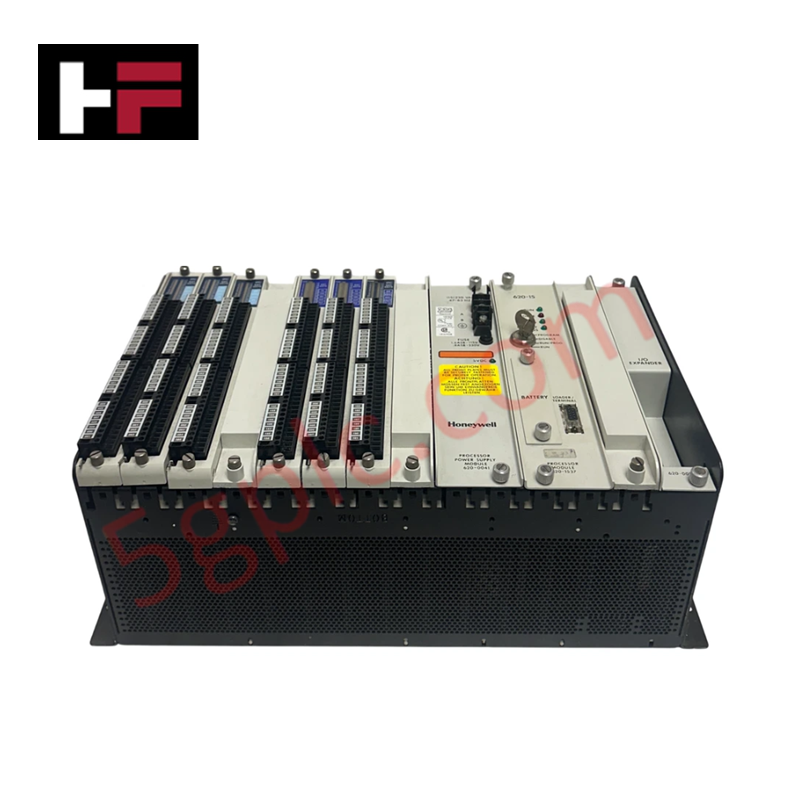
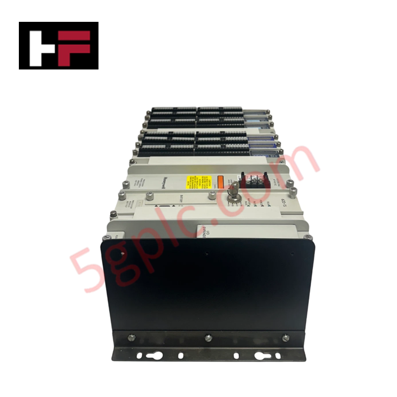
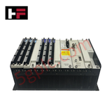
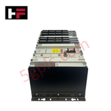
The Honeywell 620-0090, also cataloged as the 6200090 Complete Processor Rack, operates as a dedicated hardware component for backplane power distribution and module interconnectivity within Honeywell IPC 620 control systems. It provides 8 card slots to host CPU modules, power supplies, and local I/O interfaces, maintaining deterministic serial bus communication across the rack assembly.
Hardware Specifications
| Parameter | Specification |
|---|---|
| Model | 620-0090 |
| Brand | Honeywell |
| Origin | USA |
| Weight | 6.08 kg (13.40 lbs) |
| Dimensions | Standard IPC 620 8-Slot Rack Envelope |
| Operating Temp | 0 deg C to 60 deg C |
| Power Consumption | Passive Chassis Backplane (0 W Load) |
| Slot Capacity | 8 Module Slots |
| System Platform | Honeywell IPC 620 System |
| Category | PLC Chassis / Processor Rack |
Channel-to-Channel Isolation and Loop Protocol Response
The Honeywell 620-0090 chassis backplane incorporates dedicated trace isolation and grounding planes to separate internal logic power rails from external field I/O loop signals. By maintaining strict channel-to-channel isolation between backplane lines, the rack structure prevents ground potential differentials from interfering with 4-20 mA loop protocols or digital status lines running through adjacent modules. The backplane design limits noise coupling during high-density signal processing across all 8 slots.
Frequently Asked Questions
Q: Does the 8-slot backplane support live insertion or removal of processor modules?
A: No. System power must be fully isolated before inserting or removing any CPU, power supply, or interface module into the 620-0090 chassis backplane to prevent arc damage to connector pins.
Q: How is chassis grounding maintained across installed modules?
A: Grounding is established through metal contact springs and mounting hardware that bond module faceplates and internal shields directly to the heavy-gauge steel frame of the rack.
Field Installation Guidelines
- Mount the rack chassis securely into an industrial enclosure using all designated panel-mounting screw holes.
- Ensure a continuous protective earth (PE) copper conductor is attached to the chassis grounding stud prior to powering any installed modules.
- Align PCB edge connectors carefully with card guides during module insertion to avoid bending backplane pins.
- Route field I/O wiring away from backplane communication bus cables to minimize inductive noise pickup.
- Verify that all module retaining thumbscrews are hand-tightened before energizing the system.
Additional Information
- 100% Genuine Parts: All products are original and authentic, ensuring reliable industrial performance.
- 30-Day Refund Guarantee: Return any in-stock item within 30 days in original, unopened packaging for a full refund (excluding shipping and fees).
- 12-Month Warranty: Covers defects in materials or workmanship; excludes misuse, normal wear, or unauthorized modifications.
- Worldwide Shipping: We ship via USPS, UPS, FedEx, and DHL. Delivery times vary by country and may be subject to customs or import fees.
- Support & Contact: Technical and warranty assistance is available anytime. Contact us here: Contact.
- Purchase Guidance: Check product specifications and compatibility carefully before ordering to ensure proper application.





Tech & Buying Guide

Step-by-Step System Cabinet Health Check Guide for PLC and DCS Infrastructure

Top 5 Operational Advantages of HMIs in Modern Factory Automation
