


Product Details
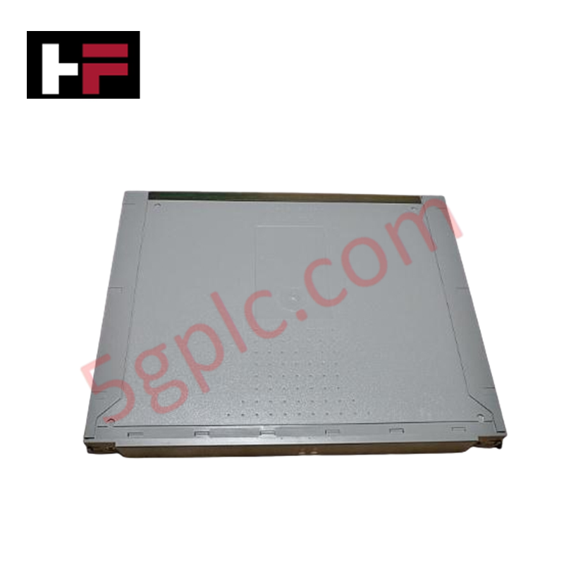
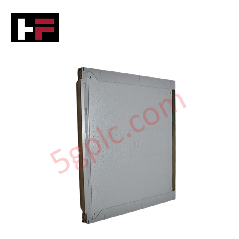
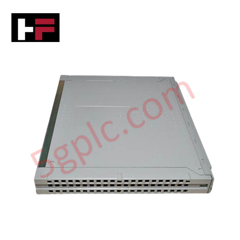
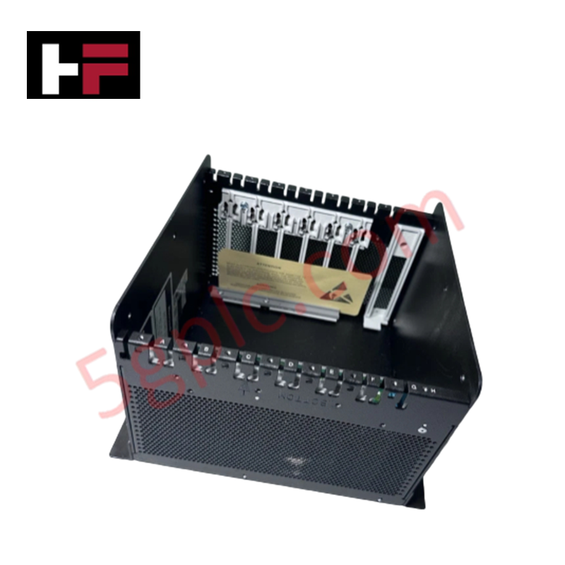
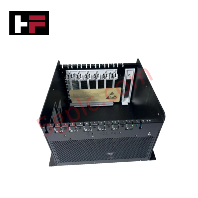
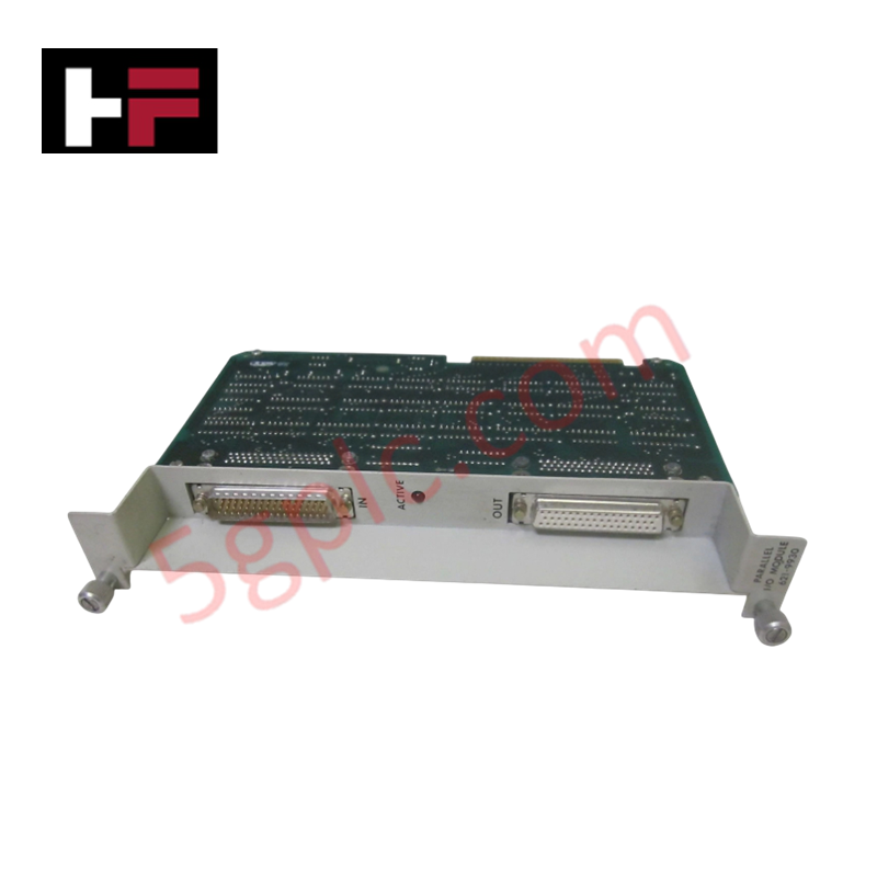
Configured for high-integrity signal acquisition in safety-critical systems, the ICS TRIPLEX T3411F (T3411F Monitored Digital Input Module) provides direct physical and electrical execution. The module interfaces with field-side digital switches to monitor state transitions and verify loop integrity, transmitting validated binary data to the safety controller via the backplane.
Hardware Specifications
| Parameter | Specification |
|---|---|
| Model | T3411F |
| Brand | ICS TRIPLEX |
| Weight | 1.5 kg |
| Dimensions | 320 mm x 32 mm x 257 mm |
| Operating Temp | 0 deg C to 60 deg C |
| Power Consumption | 8.5 Watts |
| Field Power | 24 Vdc / 48 Vdc |
| Max Input Current | 8.0 mA |
SIS Triple Modular Redundancy (TMR) Architecture
The T3411F is engineered for use within a triple modular redundancy (TMR) 2oo3 architecture to ensure fail-safe state execution. The module utilizes galvanic isolation to provide a minimum of 2500 volts separation between field wiring and internal control logic, mitigating potential interference from external transients. Through its continuous input circuit test interval of less than 2 seconds, the module detects open or short circuit conditions, allowing the TMR voting logic to isolate faulty signals and maintain uninterrupted, validated control processing.
Frequently Asked Questions
Q: Does the T3411F support hot-swapping during active system operation?
A: Yes, the T3411F is designed for hot-swap capability within the Trusted TMR backplane. Ensure the safety controller is configured to recognize the module removal event to prevent nuisance trips during replacement.
Q: How should external fusing be applied for this module?
A: The T3411F features no internal fusing. External fusing must be implemented based on the specific field loop requirements and local safety codes if protection against overcurrent at the field device is required.
Field Installation Guidelines
- Ensure the chassis slot is free of mechanical obstructions before aligning the module for insertion.
- Secure the module using the integrated captive screws to ensure the chassis maintains proper ground continuity and structural stability under 15 g shock conditions.
- Terminate field wiring in accordance with the specified voltage range of 15 Vdc to 80 Vdc; observe polarity for monitored digital inputs to ensure correct state detection.
- Utilize shielded cabling for all digital inputs, terminating shields to the cabinet ground at the entry point to maintain compliance with IEC 801 immunity standards.
- Post-installation, perform a channel-by-channel verification check via the engineering interface to confirm input logic mapping corresponds to field device positions.
Additional Information
- 100% Genuine Parts: All products are original and authentic, ensuring reliable industrial performance.
- 30-Day Refund Guarantee: Return any in-stock item within 30 days in original, unopened packaging for a full refund (excluding shipping and fees).
- 12-Month Warranty: Covers defects in materials or workmanship; excludes misuse, normal wear, or unauthorized modifications.
- Worldwide Shipping: We ship via USPS, UPS, FedEx, and DHL. Delivery times vary by country and may be subject to customs or import fees.
- Support & Contact: Technical and warranty assistance is available anytime. Contact us here: Contact.
- Purchase Guidance: Check product specifications and compatibility carefully before ordering to ensure proper application.
Tech & Buying Guide

Essential Motion Control Commands: A Practical Guide for Engineers
Automation engineers often rely on precise position and speed control to drive modern factory machinery. Modern industrial systems, such as Programmable Logic Controllers (PLCs) and Distributed Control Systems (DCS), depend heavily on standardized motion instructions. Mastering these commands ensures operational safety, protects mechanical components, and optimizes cycle times across production lines.

The Role of Intrinsic Safety Barriers in PLC and DCS Architectures
Implementing robust protection in hazardous industrial environments represents a fundamental safety requirement in factory automation. Process facilities often handle volatile gases, dusts, and chemical agents that pose significant combustion risks. Consequently, control system engineers must deploy energy-limiting interfaces to isolate safe-area control cabinets from hazardous-area field instrumentation. This article examines the function, selection, and electrical principles of intrinsic safety barriers within modern PLC and DCS networks.

Architectural Selection and Scale Classification of PLC Systems in Industrial Automation
Selecting the correct control platform represents a foundational engineering decision in factory automation. System designers must carefully balance technical parameters against long-term operational requirements when implementing a Programmable Logic Controller (PLC). This article examines the critical evaluation metrics, physical scale classifications, and operational architectures of modern control systems.