










Product Details
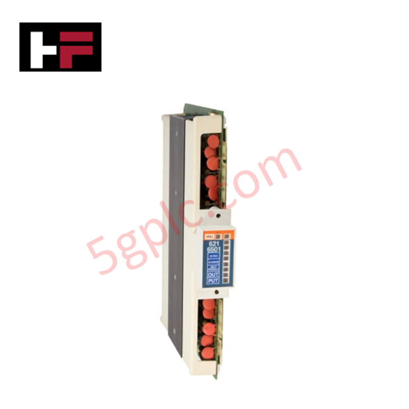
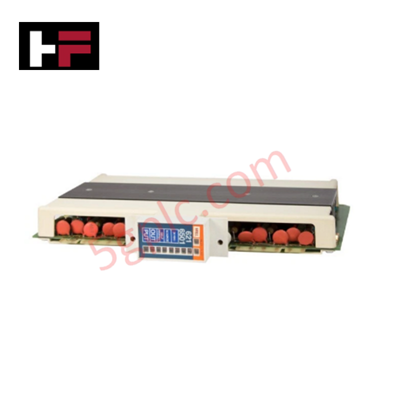
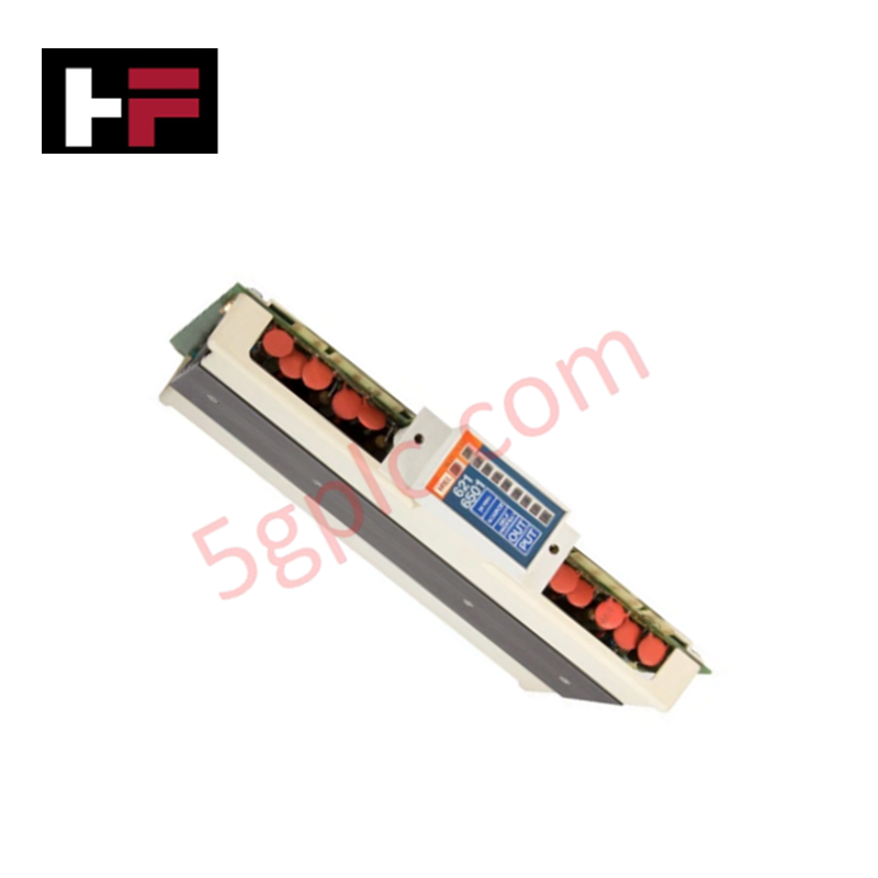
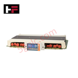
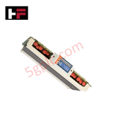
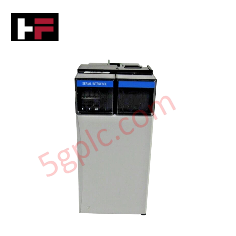
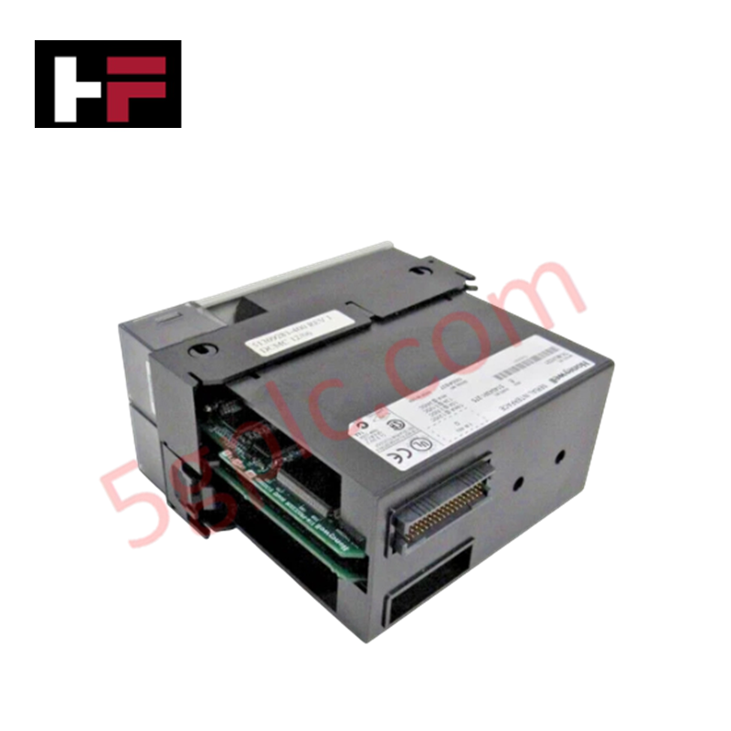
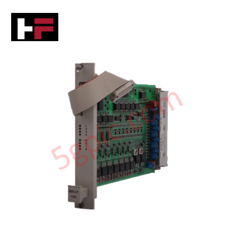
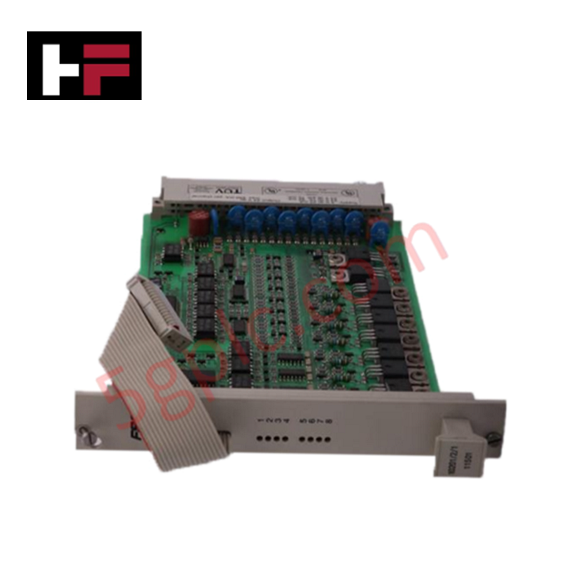
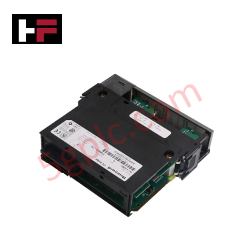
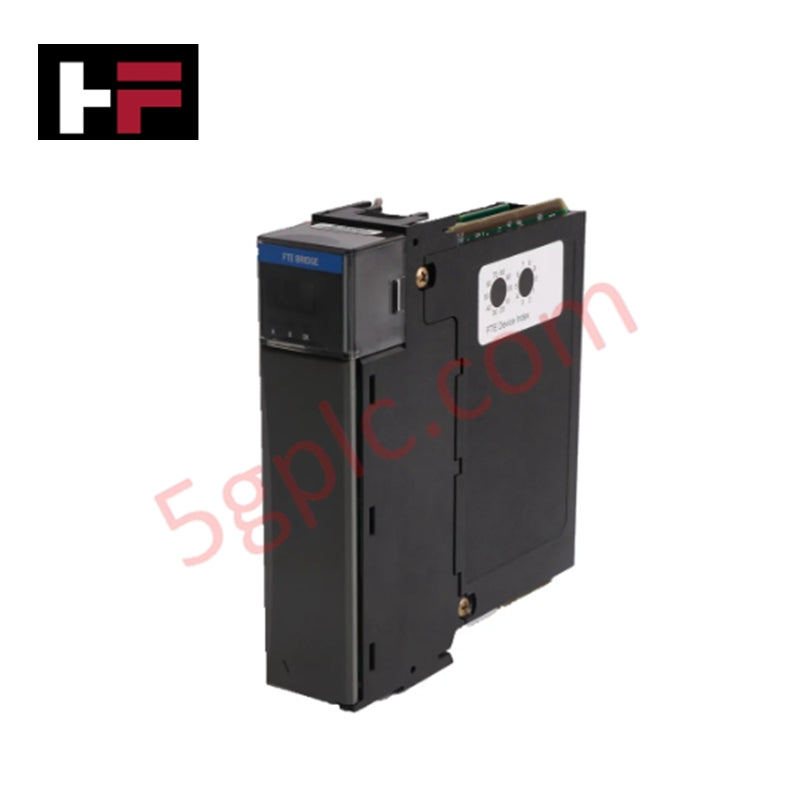
Configured for discrete load actuation and field device switching in Honeywell IPC 620 rack platforms, the Honeywell 621-6501 (621-6501 Digital Output Module) provides direct physical/electrical execution. It handles sourcing transistor switching for up to 8 discrete 24 VDC channels, executing PLC output logic states directly to field actuators.
Hardware Specifications
| Parameter | Specification |
|---|---|
| Model | 621-6501 |
| Brand | Honeywell |
| Origin | USA |
| Weight | 0.6 kg |
| Dimensions | 3.0 cm x 24.1 cm x 17.3 cm (1.2 in x 9.5 in x 6.8 in) |
| Operating Temp | 0 deg C to 60 deg C |
| Power Consumption | 110 mA max (+5 VDC backplane) |
| Output Type | 24 VDC Sourcing Transistor |
| Output Channels | 8 Channels |
| Operating Voltage Range | 11-28 VDC |
| Maximum Output Current | 2 A per channel, 6 A per common, 8 A per module |
| Surge Current | 5 A for 10 ms (non-repetitive) |
| Off-State Leakage | Less than or equal to 5 mA |
| On-State Voltage Drop | Less than or equal to 2 VDC at 2 A load |
| Circuit Fusing | 1 x 3 A Fast-Blow Fuse per channel |
| Compatible Chassis | Honeywell IPC 620 Chassis |
Channel-to-Channel Isolation and Output Protection
The Honeywell 621-6501 output stage incorporates galvanically isolated channel grouping to prevent field-side voltage transients from damaging backplane processing logic. Each of the 8 sourcing channels contains an independent 3 A fast-blow fuse to clear overcurrent fault conditions before thermal breakdown occurs in the output transistors. The module architecture maintains channel-to-channel isolation between distinct output groups, suppressing inductive switching noise during inductive load de-energization across field loops.
Frequently Asked Questions
Q: What is the procedure if an individual channel output fuse opens?
A: De-energize field power to the module, remove the module from the rack chassis, and replace the blown channel fuse with a rated 3 A fast-blow fuse before restoring power.
Q: Can output channels be wired in parallel to increase continuous current capability above 2 A?
A: Paralleling outputs on the same module is not recommended due to minor variations in transistor turn-on timing, which can cause transient current imbalances exceeding single-channel limits.
Field Installation Guidelines
- Turn off backplane rack power and external 24 VDC field supplies prior to inserting the module into the IPC 620 chassis.
- Align the printed circuit board with the chassis card guides and slide the module inward until the rear backplane connector locks securely.
- Tighten top and bottom panel mounting screws to establish chassis frame electrical bonding.
- Route field output wiring in separate conduit pathways from low-level analog or communication cables.
- Verify fuse integrity and correct 24 VDC power supply polarity at the field terminal block prior to energizing field loads.
Additional Information
- 100% Genuine Parts: All products are original and authentic, ensuring reliable industrial performance.
- 30-Day Refund Guarantee: Return any in-stock item within 30 days in original, unopened packaging for a full refund (excluding shipping and fees).
- 12-Month Warranty: Covers defects in materials or workmanship; excludes misuse, normal wear, or unauthorized modifications.
- Worldwide Shipping: We ship via USPS, UPS, FedEx, and DHL. Delivery times vary by country and may be subject to customs or import fees.
- Support & Contact: Technical and warranty assistance is available anytime. Contact us here: Contact.
- Purchase Guidance: Check product specifications and compatibility carefully before ordering to ensure proper application.


Tech & Buying Guide

Understanding Root Causes of Unplanned PLC Stop Mode in Industrial Automation
Modern Programmable Logic Controllers manage execution through distinct operational states: Run, Stop, Start-Up, and Hold. During power-up, a controller initializes memory registers within Stop mode before briefly transitioning to Start-Up mode. During this phase, internal self-diagnostics evaluate system integrity across hardware and user programs. If the controller detects no critical faults, it enters Run mode to execute the control program continuously. However, any severe system anomaly forces the CPU back into Stop mode immediately to prevent erratic machine behavior across the plant floor.

Human-Machine Interface Design: Essential Guide to HMI Selection, Visualization, and Control System Integration
Human-Machine Interfaces (HMIs) serve as the primary operational window into complex industrial automation systems. Modern HMIs convert raw machine data into clear graphical displays, enabling operators to oversee entire manufacturing processes in real time. Instead of relying on physical control panels full of hardwired switches, engineers program interactive screens using intuitive graphics, dynamic color coding, and responsive touch interfaces. Over my 15 years in control systems engineering, I have observed HMIs transform from basic display screens into sophisticated command centers that drive operational efficiency across DCS and PLC environments.

Understanding Safety Relays in Industrial Automation: Architecture, Operation, and Functional Safety
Standard electromechanical relays provide basic electrical isolation between low-voltage control circuits and high-power output loads. A traditional switching relay features a magnetic coil driving mechanical Common (COM), Normally-Open (NO), and Normally-Closed (NC) contacts. However, standard relays pose severe functional risks when deployed in critical safety interlock circuits. High current inrush or mechanical wear can weld contacts together permanently. If contact welding occurs in an emergency stop circuit, pressing the button fails to halt hazardous machinery movements. Consequently, global functional safety standards prohibit standard relays for critical machine guarding functions.