


Product Details
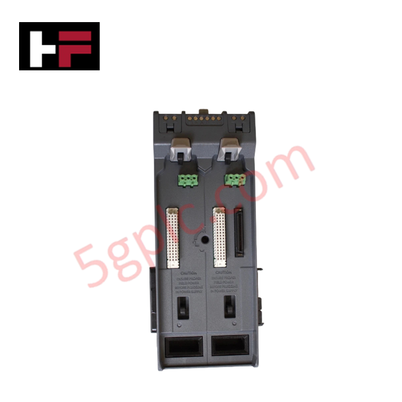
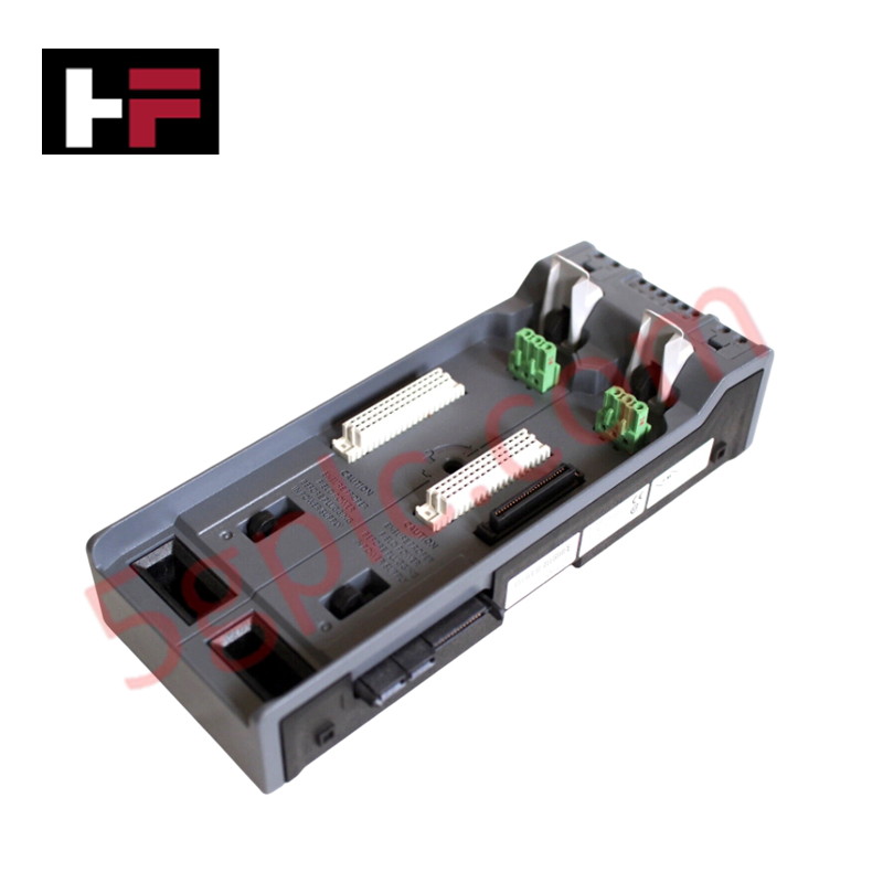
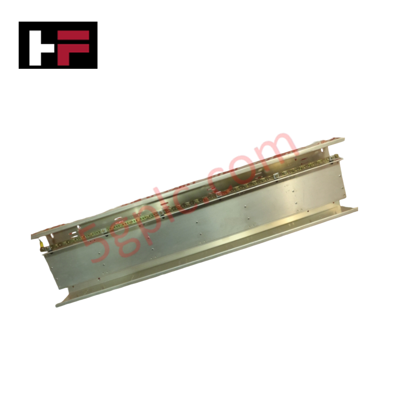
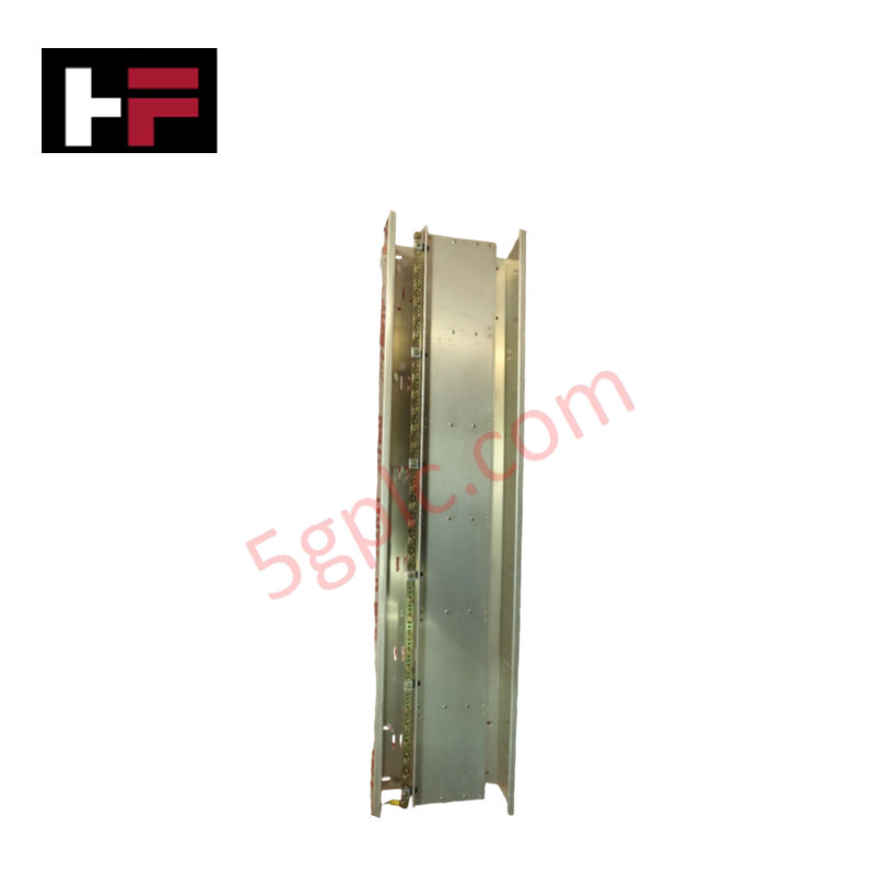
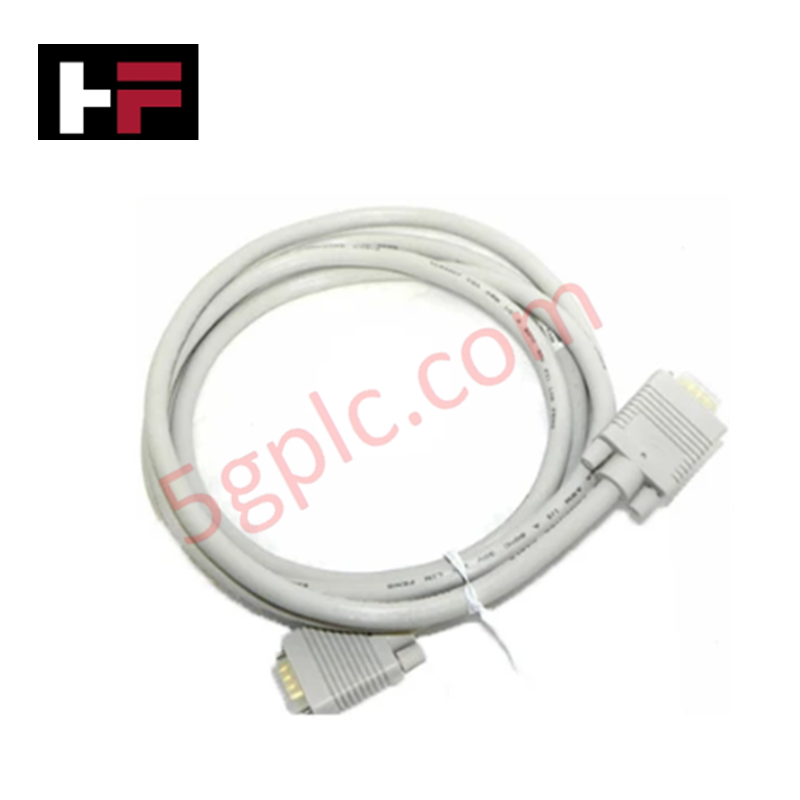
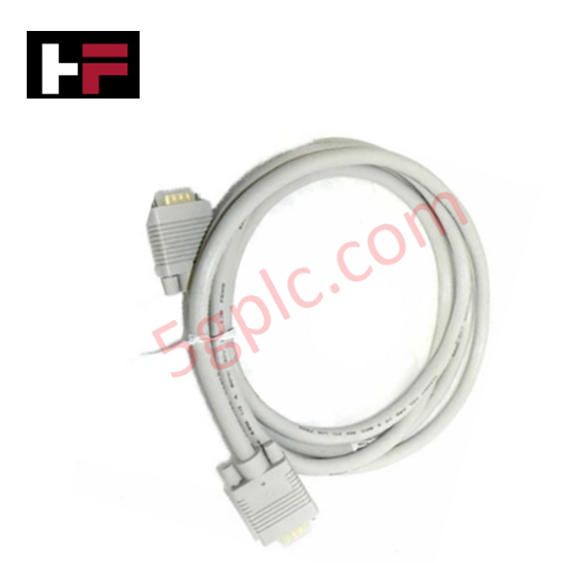
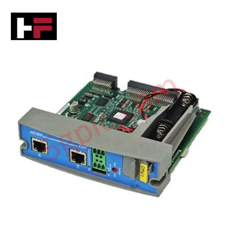
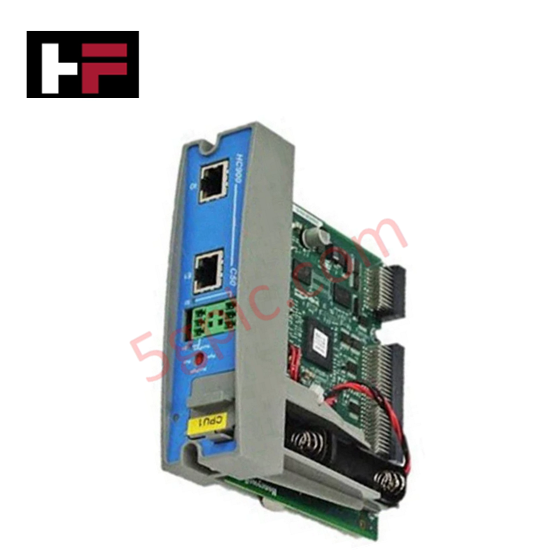
Configured for power distribution and control module mounting in DeltaV I/O subsystems, the Emerson SE3051C0 (SE3051C0 2-Wide Power/Controller Carrier) provides direct physical/electrical execution of bus power regulation and module backplane connectivity.
Hardware Specifications
| Parameter | Specification |
| Model | SE3051C0 |
| Brand | Emerson |
| Origin | USA |
| Weight | 0.45 kg (0.99 lbs) |
| Dimensions | Standard DeltaV S-Series 2-wide form factor |
| Operating Temp | -40 deg C to +70 deg C |
| Power Consumption | Passive distribution |
| Input Rating | 24 VDC |
| Current Rating | 8 A |
Process Control: Channel-to-Channel Isolation
The SE3051C0 carrier is engineered to maintain electrical separation between the power input stages and the controller backplane interface. This architecture employs rigorous dielectric boundaries to ensure that field-side power distribution remains galvanically isolated from the sensitive internal logic buses of the mounted controllers. By utilizing high-density contact points with low-impedance pathways, the carrier prevents localized short-circuit faults or voltage surges from propagating across the backplane. This structural isolation is mandatory for maintaining the integrity of the 24 VDC supply rail under full 8 A load conditions, safeguarding downstream electronic modules from transient power instability.
Frequently Asked Questions (FAQ)
Q: What is the maximum current capacity for this carrier?
A: The SE3051C0 carrier is rated for a continuous current capacity of 8 A. Ensure that the cumulative current draw of all mounted modules and field devices does not exceed this 8 A threshold to prevent thermal degradation of the power distribution pins.
Q: Is this carrier compatible with all S-Series modules?
A: The carrier is physically and electrically keyed for S-Series controllers and power supply modules. Verify that the specific controller or power module variant is compatible with the SE3051C0 backplane pin configuration before installation.
Field Installation Guidelines
-
Mounting: Secure the carrier to the mounting plate using appropriate hardware. Ensure the orientation is vertical to permit sufficient natural convection through the cooling vents, facilitating operation within the -40 deg C to +70 deg C range.
-
Grounding: Terminate the carrier's chassis ground terminal to the cabinet's master ground bus using a low-impedance cable. Proper bonding is mandatory for electromagnetic compatibility and transient voltage suppression.
-
Wiring: Connect the 24 VDC input source to the dedicated power terminals. Use correctly sized conductors to minimize voltage drop, and ensure field-side power circuits are protected by appropriately rated external circuit breakers.
-
Verification: After installation, verify the presence of 24 VDC at the carrier output terminals under load using a calibrated multimeter. Ensure the status LED on mounted modules confirms correct power-up and backplane communication.
Additional Information
- 100% Genuine Parts: All products are original and authentic, ensuring reliable industrial performance.
- 30-Day Refund Guarantee: Return any in-stock item within 30 days in original, unopened packaging for a full refund (excluding shipping and fees).
- 12-Month Warranty: Covers defects in materials or workmanship; excludes misuse, normal wear, or unauthorized modifications.
- Worldwide Shipping: We ship via USPS, UPS, FedEx, and DHL. Delivery times vary by country and may be subject to customs or import fees.
- Support & Contact: Technical and warranty assistance is available anytime. Contact us here: Contact.
- Purchase Guidance: Check product specifications and compatibility carefully before ordering to ensure proper application.
Tech & Buying Guide

Essential Motion Control Commands: A Practical Guide for Engineers
Automation engineers often rely on precise position and speed control to drive modern factory machinery. Modern industrial systems, such as Programmable Logic Controllers (PLCs) and Distributed Control Systems (DCS), depend heavily on standardized motion instructions. Mastering these commands ensures operational safety, protects mechanical components, and optimizes cycle times across production lines.

The Role of Intrinsic Safety Barriers in PLC and DCS Architectures
Implementing robust protection in hazardous industrial environments represents a fundamental safety requirement in factory automation. Process facilities often handle volatile gases, dusts, and chemical agents that pose significant combustion risks. Consequently, control system engineers must deploy energy-limiting interfaces to isolate safe-area control cabinets from hazardous-area field instrumentation. This article examines the function, selection, and electrical principles of intrinsic safety barriers within modern PLC and DCS networks.

Architectural Selection and Scale Classification of PLC Systems in Industrial Automation
Selecting the correct control platform represents a foundational engineering decision in factory automation. System designers must carefully balance technical parameters against long-term operational requirements when implementing a Programmable Logic Controller (PLC). This article examines the critical evaluation metrics, physical scale classifications, and operational architectures of modern control systems.