


Product Details
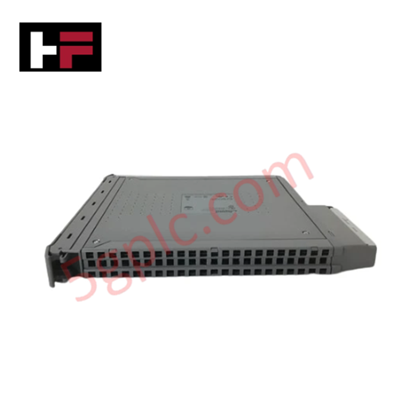
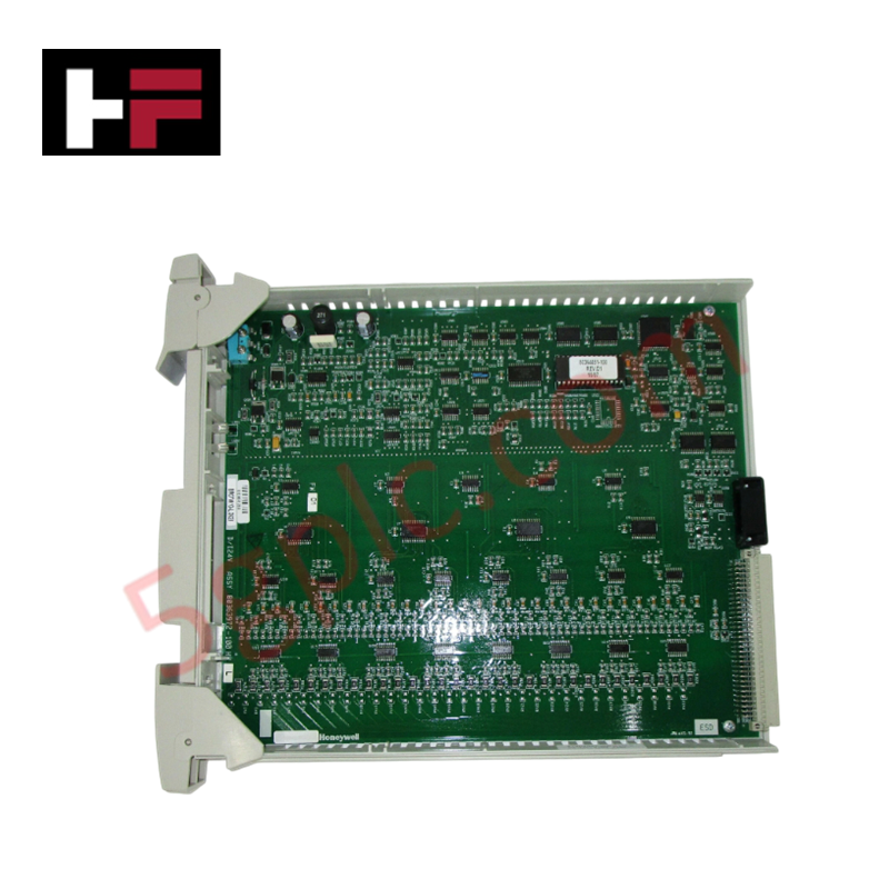
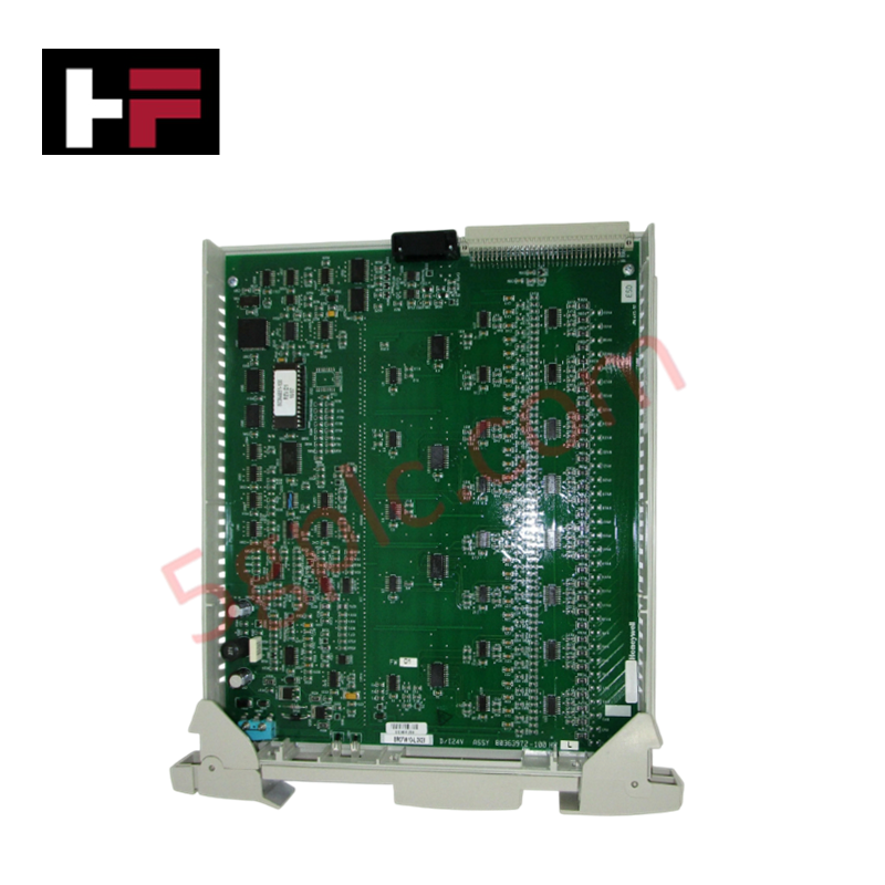
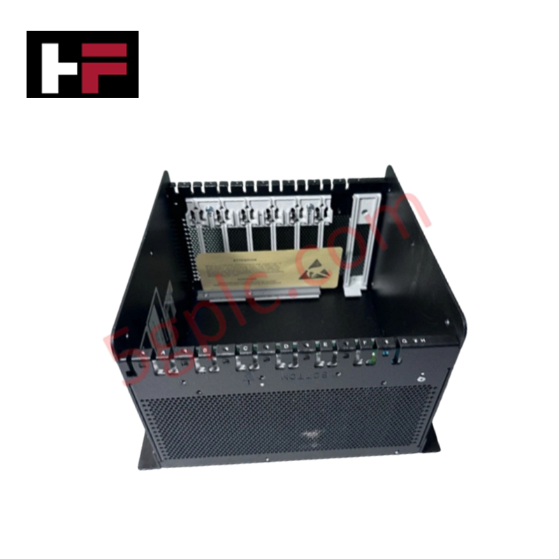
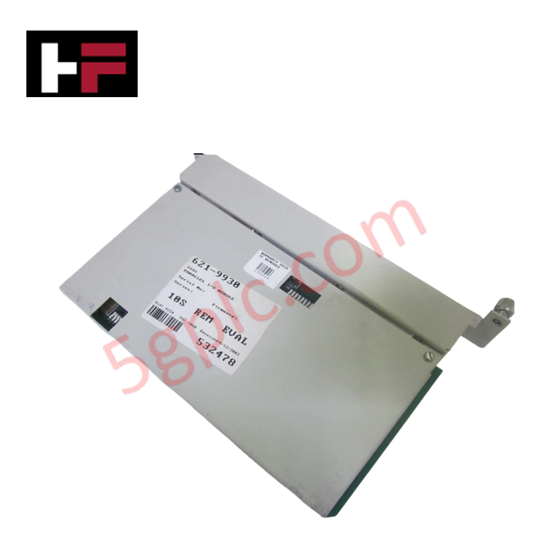
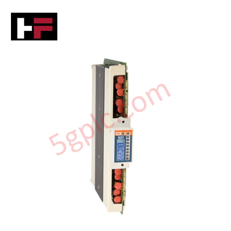
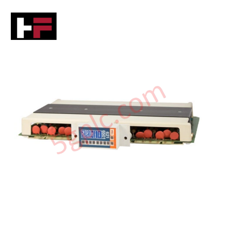
Configured for signal execution in safety-critical networks, the ICS TRIPLEX T8461C (T8461C Digital Output Module) provides direct physical and electrical execution. The module manages the switching of 24 VDC and 48 VDC field circuits, serving as a high-density interface for command distribution within the Trusted TMR safety architecture.
Hardware Specifications
| Parameter | Specification |
|---|---|
| Model | T8461C |
| Brand | ICS TRIPLEX |
| Origin | United States |
| Weight | 1.32 kg |
| Dimensions | 3 cm x 30.3 cm x 26.5 cm |
| Operating Temp | Standard Industrial |
| Power Consumption | Configuration Dependent |
| Voltage Output | 24 VDC / 48 VDC |
SIS Triple Modular Redundancy (TMR) Architecture
The T8461C is engineered for operation within a triple modular redundancy (TMR) 2oo3 architecture. Internal logic processing is distributed across three independent signal paths, with a hardware-based voting mechanism determining the final output state. This architecture ensures that a single component failure within the output circuitry does not result in an unintended state change. Furthermore, galvanic isolation is provided between the output stages and the system bus, maintaining signal integrity and protecting internal logic from field-side voltage spikes. Fail-safe state execution is triggered by the voter logic upon detection of persistent internal path discrepancies.
Frequently Asked Questions
Q: Does the T8461C support online hot-swapping?
A: Yes, the T8461C is designed for hot-swap capability. Maintenance procedures must ensure that the control system logic is in a non-active state for the specific module address to prevent transient output states during the replacement process.
Q: Are there specific configuration requirements for 24 VDC versus 48 VDC operation?
A: The module supports both voltage levels; however, configuration settings within the application software must be verified to ensure correct output switching characteristics and monitoring thresholds for the connected field load.
Field Installation Guidelines
- Ensure the module is properly aligned with the backplane connectors to prevent mechanical stress on the signal pins during insertion.
- Secure the module using the chassis retention screws to maintain a consistent chassis ground connection.
- Terminate field loads to the output terminals using shielded cabling, ensuring the shield is grounded at the designated system reference point to mitigate electromagnetic interference.
- Verify that field wiring is rated for the maximum switching voltage (48 VDC) and current capacity of the load.
- After physical installation, perform a diagnostic check via the Trusted TMR system console to confirm module recognition and output path health.
Additional Information
- 100% Genuine Parts: All products are original and authentic, ensuring reliable industrial performance.
- 30-Day Refund Guarantee: Return any in-stock item within 30 days in original, unopened packaging for a full refund (excluding shipping and fees).
- 12-Month Warranty: Covers defects in materials or workmanship; excludes misuse, normal wear, or unauthorized modifications.
- Worldwide Shipping: We ship via USPS, UPS, FedEx, and DHL. Delivery times vary by country and may be subject to customs or import fees.
- Support & Contact: Technical and warranty assistance is available anytime. Contact us here: Contact.
- Purchase Guidance: Check product specifications and compatibility carefully before ordering to ensure proper application.
Tech & Buying Guide

Essential Motion Control Commands: A Practical Guide for Engineers
Automation engineers often rely on precise position and speed control to drive modern factory machinery. Modern industrial systems, such as Programmable Logic Controllers (PLCs) and Distributed Control Systems (DCS), depend heavily on standardized motion instructions. Mastering these commands ensures operational safety, protects mechanical components, and optimizes cycle times across production lines.

The Role of Intrinsic Safety Barriers in PLC and DCS Architectures
Implementing robust protection in hazardous industrial environments represents a fundamental safety requirement in factory automation. Process facilities often handle volatile gases, dusts, and chemical agents that pose significant combustion risks. Consequently, control system engineers must deploy energy-limiting interfaces to isolate safe-area control cabinets from hazardous-area field instrumentation. This article examines the function, selection, and electrical principles of intrinsic safety barriers within modern PLC and DCS networks.

Architectural Selection and Scale Classification of PLC Systems in Industrial Automation
Selecting the correct control platform represents a foundational engineering decision in factory automation. System designers must carefully balance technical parameters against long-term operational requirements when implementing a Programmable Logic Controller (PLC). This article examines the critical evaluation metrics, physical scale classifications, and operational architectures of modern control systems.