










Product Details
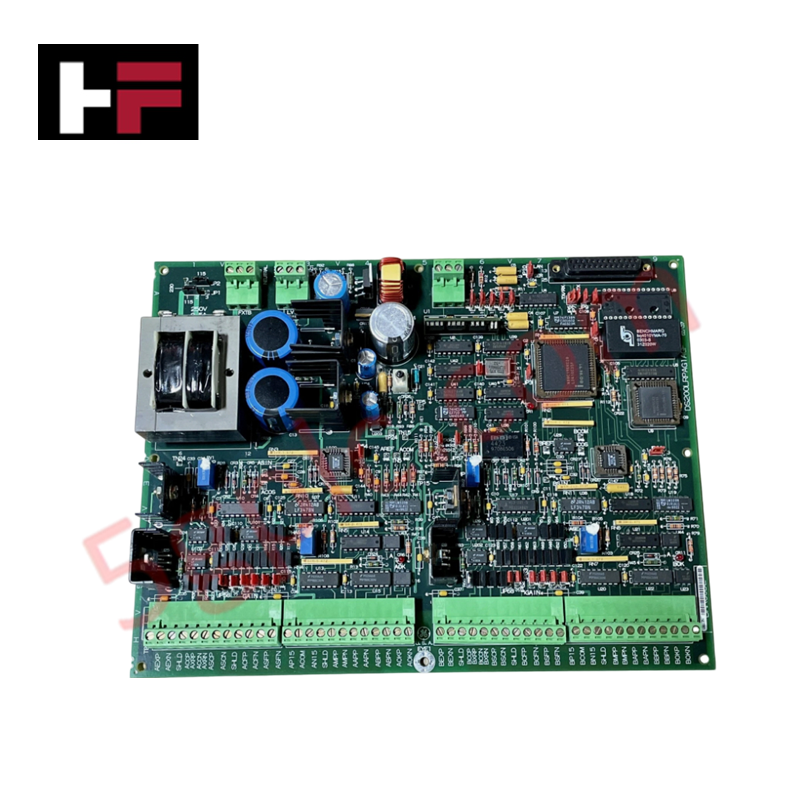
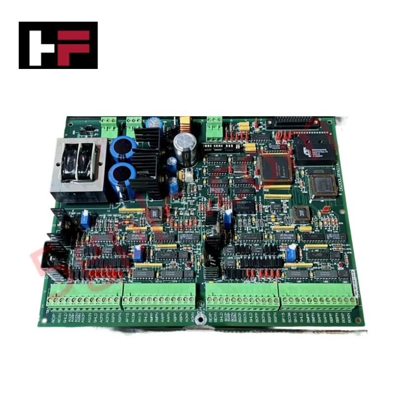
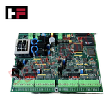
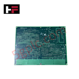
Configured for electrical parameter monitoring and fault isolation in drive control systems, the GE DS200LRPAG1A (DS200LRPA Line Protection Card) provides direct physical/electrical execution of circuit breaker trip sequences upon detection of abnormal line conditions.
Hardware Specifications
| Parameter | Specification |
|---|---|
| Model | DS200LRPAG1A |
| Brand | GE (General Electric) |
| Origin | USA |
| Operating Temp | Standard industrial ambient |
| Primary Components | Transformer, terminal strips, LED indicators, reset switch |
| Interface | Vertical female cable connector, stab-on connectors |
PLC/DCS Deterministic Network Integration
The DS200LRPAG1A performs real-time analysis of voltage, current, and frequency inputs to execute protective logic. Within the Drive Control system, the board maintains deterministic performance by comparing sampled input data against programmed thresholds. To ensure stability, the backplane bus communication velocity must be matched to the host controller requirements. Integration requires verification of firmware flash compatibility to ensure the protection algorithms—including ground fault and directional protection logic—are synchronized with the system's overall safety timing. Proper configuration prevents latency in trip signal delivery during fault events.
Frequently Asked Questions
Q: Can the onboard reset switch be utilized to clear trip signals while the power line is still in a fault state?
A: No. The reset switch should only be operated after the primary fault condition has been cleared and isolated. Attempting to reset the board while a fault persists will result in an immediate re-trip condition, as the protection logic will detect the violation upon re-initialization.
Q: How are the LED indicators used for diagnostic fault condition determination?
A: The LEDs provide status updates on internal board health and the operational state of the trip circuit. Refer to the specific GE system manual to map LED blink codes to fault categories, such as power supply failure, sensor input loss, or trip output status.
Field Installation Guidelines
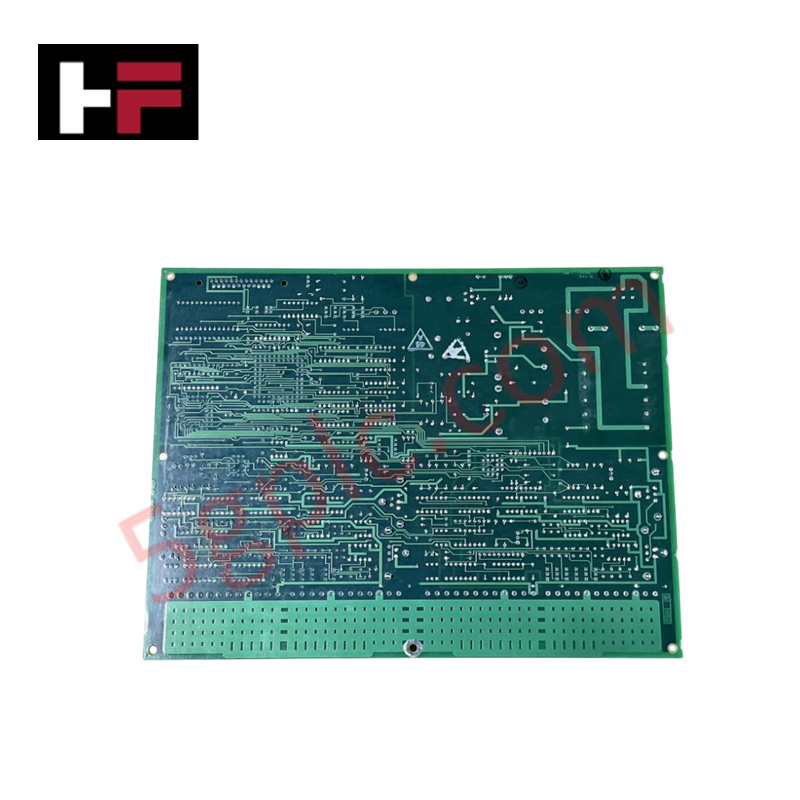
- Mounting: Utilize the factory-drilled holes in the board corners and along the edges for secure mounting via standoffs or screws. Ensure the board is electrically isolated from the cabinet chassis to prevent ground loops.
- Sensor Termination: Connect line monitoring sensors to the designated terminal strips. Verify wire gauge and ensure screw terminals are tightened to specified torque to maintain low-resistance signal paths for current and voltage inputs.
- Shielding: Terminate cable shields at the designated ground points to mitigate electromagnetic interference, which can cause erratic trip triggering.
- Termination: Ensure the vertical female cable connector and stab-on connectors are fully seated. Loose connections on these interfaces can lead to signal degradation and false positive trip signals.
Additional Information
- 100% Genuine Parts: All products are original and authentic, ensuring reliable industrial performance.
- 30-Day Refund Guarantee: Return any in-stock item within 30 days in original, unopened packaging for a full refund (excluding shipping and fees).
- 12-Month Warranty: Covers defects in materials or workmanship; excludes misuse, normal wear, or unauthorized modifications.
- Worldwide Shipping: We ship via USPS, UPS, FedEx, and DHL. Delivery times vary by country and may be subject to customs or import fees.
- Support & Contact: Technical and warranty assistance is available anytime. Contact us here: Contact.
- Purchase Guidance: Check product specifications and compatibility carefully before ordering to ensure proper application.


Tech & Buying Guide

Demystifying CPU Communication Ports in Siemens PLC Architectures
Industrial automation relies heavily on robust data exchange between devices. Without seamless connectivity, field instruments, network switches, human-machine interfaces, and programmable logic controllers cannot coordinate effectively. Therefore, understanding the various CPU communication ports available in Siemens hardware ensures efficient factory automation design and seamless system integration.

Mastering the Siemens PLC Scan Cycle: How the CPU Executes Automation Programs
Industrial automation relies heavily on programmable logic controllers (PLCs) to manage complex manufacturing processes. Many engineers dive straight into programming without mastering the underlying architecture. However, understanding how a PLC CPU executes a program ensures reliable system design. Therefore, mastering the scan cycle optimizes both performance and troubleshooting in modern control systems.

How to Connect to Siemens S7 PLCs: 5 Essential Communication Methods
Establishing a reliable hardware link between a programming terminal and a Siemens SIMATIC controller is essential for engineering workflows. Field engineers rely on distinct physical layers, ranging from legacy serial connections to high-speed Industrial Ethernet protocols. Modern factory automation environments prioritize fast data transfer and seamless driver integration. Selecting the correct connection method simplifies program downloads, online monitoring, and system troubleshooting in complex control systems.