


Product Details
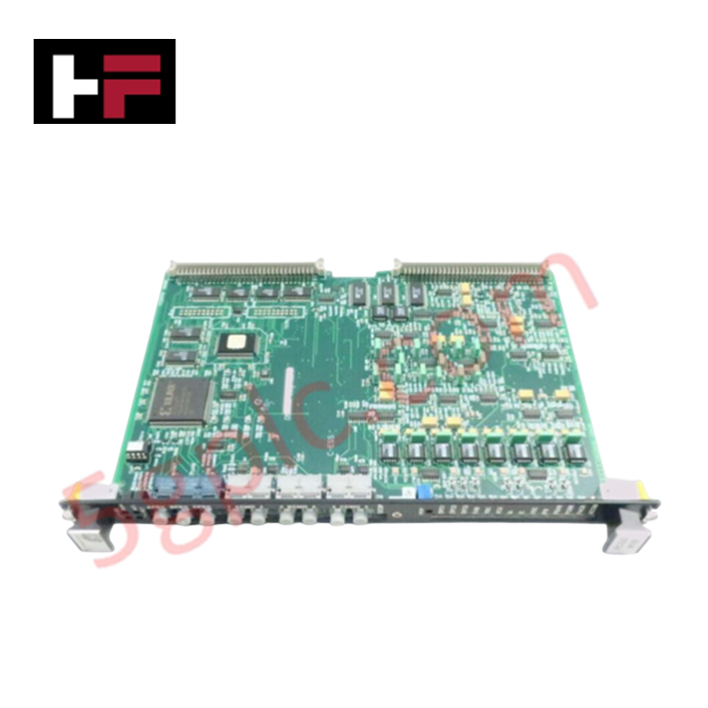
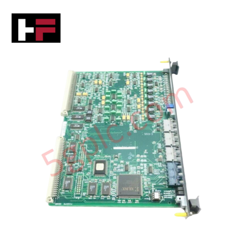
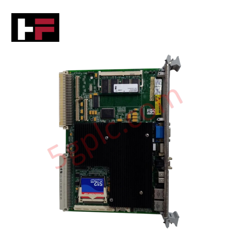
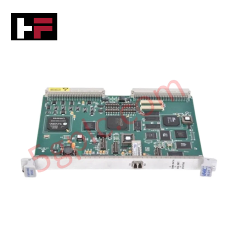
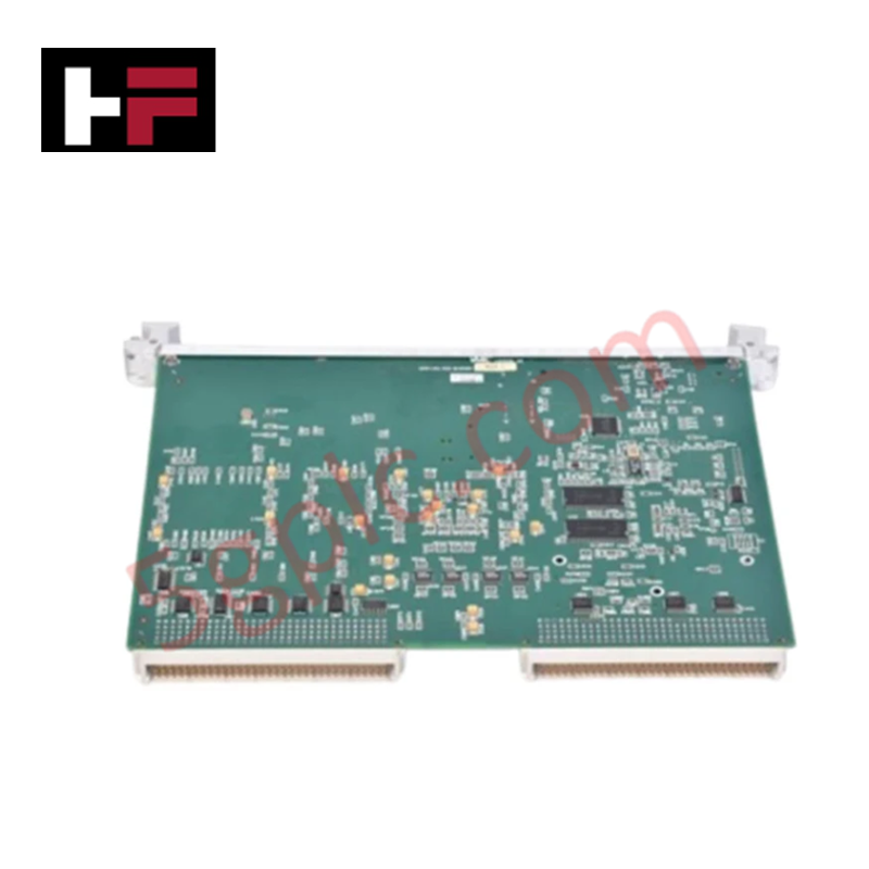
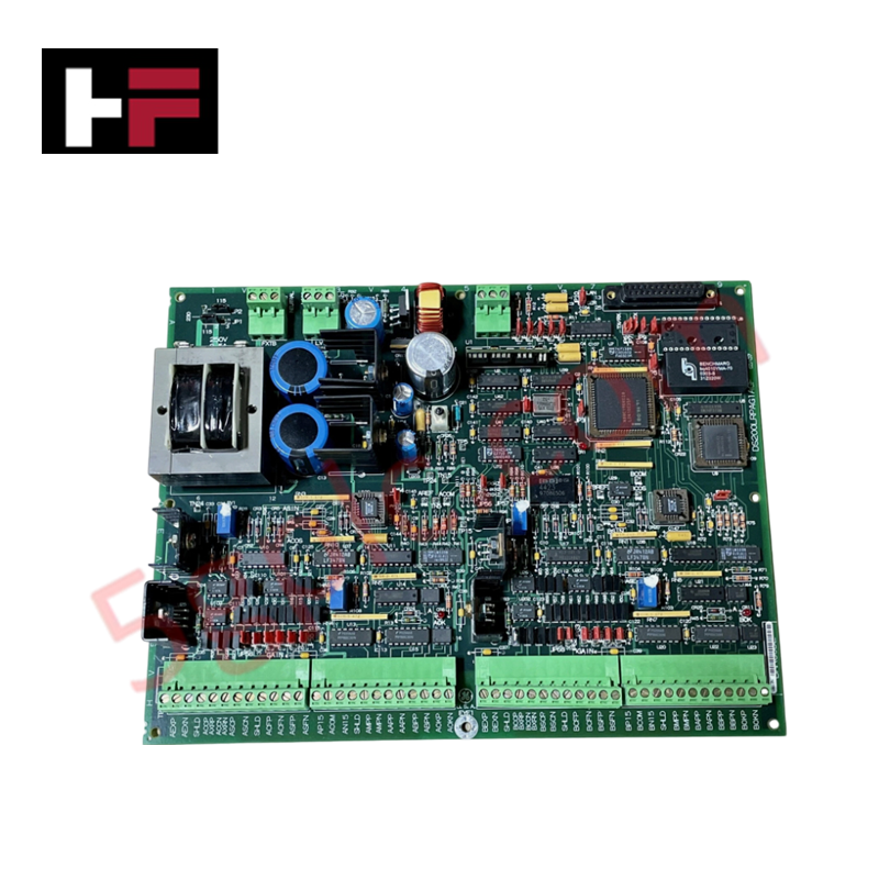
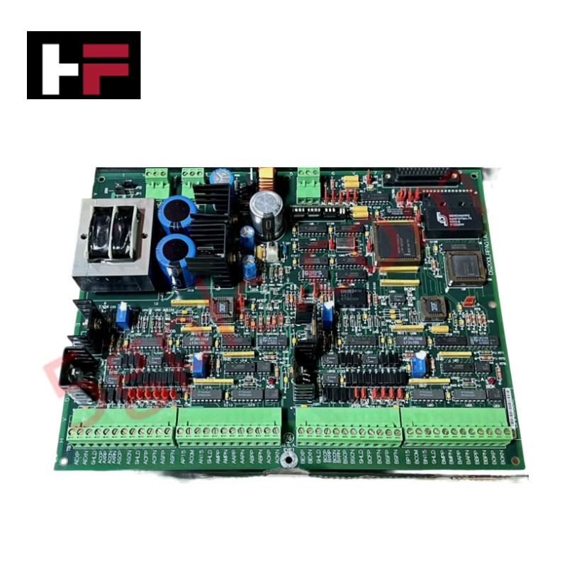
Configured for 6-pulse phase-controlled bridge management in Mark VI turbine control systems, the GE DS200FCGDH1B (DS200FCGD Gate Distribution and Status Card) provides direct physical/electrical execution of SCR firing command distribution and bridge feedback processing.
Hardware Specifications
| Parameter | Specification |
|---|---|
| Model | DS200FCGDH1B |
| Brand | GE (General Electric) |
| Origin | USA |
| Weight | 0.45 kg |
| Dimensions | 9.2 inch x 6.3 inch |
| Operating Temp | -30 to 65 deg C |
| Power Consumption | 24 VDC |
| Channels | 12 |
| Span | -8 mV to +45 mV |
PLC/DCS Deterministic Network Integration
The DS200FCGDH1B maintains deterministic timing within the Mark VI architecture by interfacing directly with the DSPC VME processor. The module decodes multiplexed cell status signals and distributes gating commands across the bridge legs, ensuring synchronized power conversion. Integration is contingent upon precise backplane bus communication velocity settings, which facilitate the high-speed transfer of feedback data including voltage, frequency, and current status. Firmware flash compatibility is governed by the host VME processor; users must verify that the FCGD register structure is recognized by the active control software to ensure accurate pulse-width modulation and timestamping of firing commands.
Frequently Asked Questions
Q: What is the significance of the "IMOK" LED indicator on the board front?
A: The IMOK LED confirms the integrity of the board-level system heartbeat. This indicator only illuminates after the VME host CPU has successfully initialized the heartbeat register, verifying that the board is communicating correctly with the processor and performing its diagnostic functions.
Q: Can the board be configured for different bridge pulse variations?
A: The FCGD is designed specifically for 6-pulse phase-controlled, non-reversing bridge interfaces. It handles gating signals by decoding multiplexed inputs; modifications to the bridge topology or pulse requirements are not supported via jumpers and would require a hardware revision or a system-level logic change within the DSPC processor.
Field Installation Guidelines
- Mounting: The board is designed for DIN-rail mounting. Ensure the rail is securely fastened to the cabinet backplane and provides a solid earth-ground connection to mitigate transient voltage interference.
- VME Backplane Insertion: When inserting the card into the VME slot, ensure the ejector levers are fully retracted. Ensure the connectors are properly aligned to prevent pin damage during insertion, as the high density of the VME bus requires precise seating.
- Signal Grounding: Because the board operates with a sensitive span of -8 mV to +45 mV, maintain physical separation between signal inputs and high-power AC lines to prevent induced noise and potential signal clipping.
- Reset Protocols: During system power-up or following a hard reset, allow the board to cycle through its internal diagnostic routine, confirmed by the illumination of the IMOK LED, before enabling high-voltage firing sequences.
Additional Information
- 100% Genuine Parts: All products are original and authentic, ensuring reliable industrial performance.
- 30-Day Refund Guarantee: Return any in-stock item within 30 days in original, unopened packaging for a full refund (excluding shipping and fees).
- 12-Month Warranty: Covers defects in materials or workmanship; excludes misuse, normal wear, or unauthorized modifications.
- Worldwide Shipping: We ship via USPS, UPS, FedEx, and DHL. Delivery times vary by country and may be subject to customs or import fees.
- Support & Contact: Technical and warranty assistance is available anytime. Contact us here: Contact.
- Purchase Guidance: Check product specifications and compatibility carefully before ordering to ensure proper application.
Tech & Buying Guide

Essential SCADA Features for Modern IoT-Enabled Industrial Automation
The convergence of traditional SCADA systems with the Industrial Internet of Things (IIoT) has redefined factory automation. Choosing a robust platform requires more than just standard monitoring capabilities. In this era of Industry 4.0, your supervisory system must bridge the gap between legacy control systems and enterprise-level data integration.

Selecting Rockwell Automation Allen-Bradley PLCs for Small and Mid-Sized Applications
Rockwell Automation remains a cornerstone in global industrial automation. Their Allen-Bradley brand provides a comprehensive portfolio of control systems designed to meet diverse production requirements. Choosing the right programmable logic controller (PLC) is critical for system reliability and scalability. This guide analyzes the Micro and Compact Logix families to help you select the optimal solution for small and medium-scale projects.

Strategic Selection: Choosing the Right SCADA Software for Your PLC Project
In industrial automation, the SCADA (Supervisory Control and Data Acquisition) system acts as the bridge between raw machine data and actionable human intelligence. Selecting the incorrect software platform can lead to integration bottlenecks, scalability issues, and excessive long-term maintenance costs. As an automation consultant with 15 years of experience, I have guided many projects through the selection process. Below are the essential criteria for choosing a platform that ensures both performance and longevity.