


Product Details
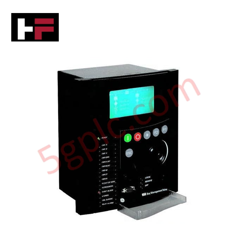
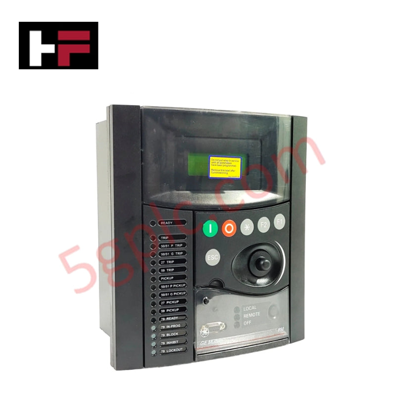
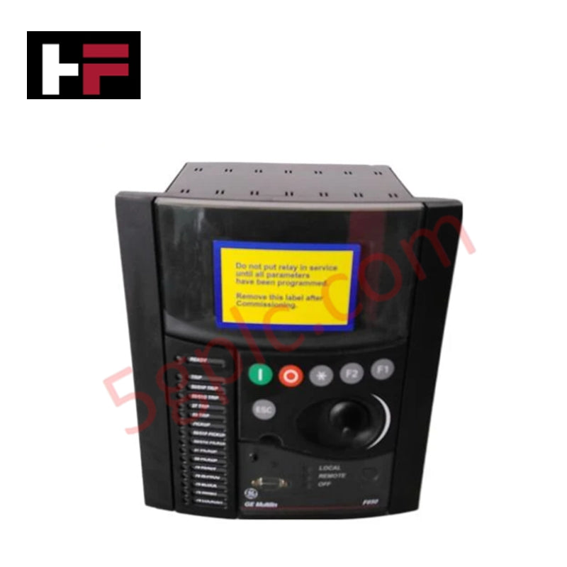
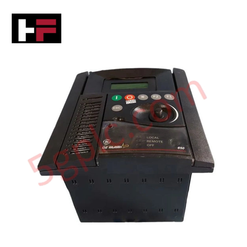
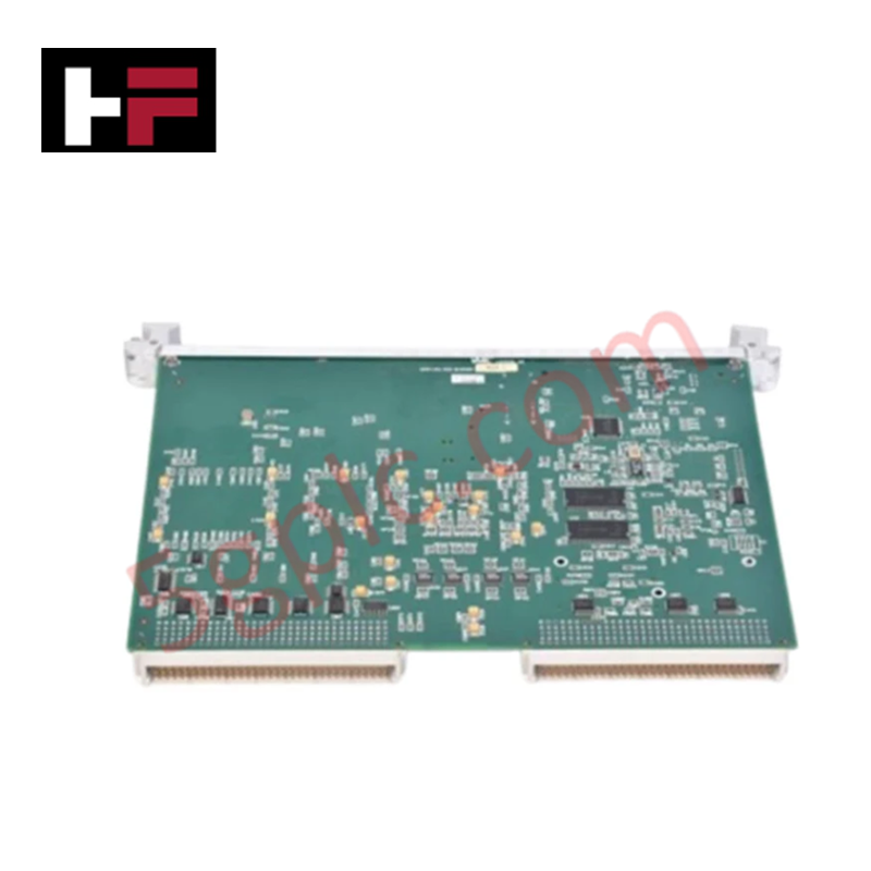
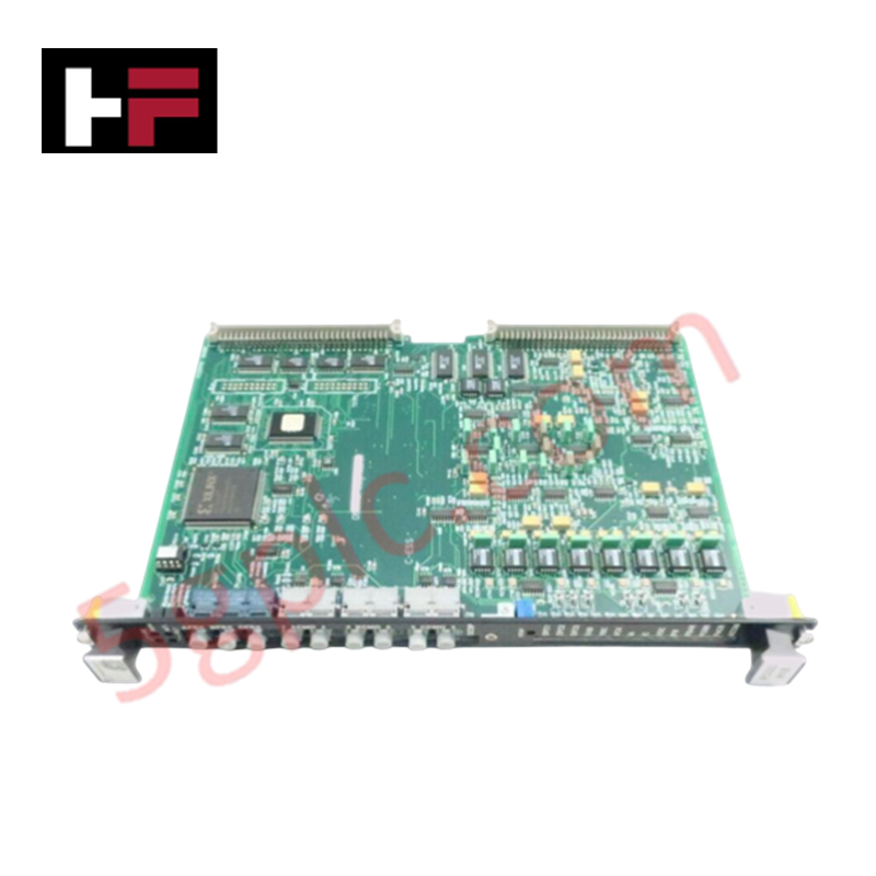
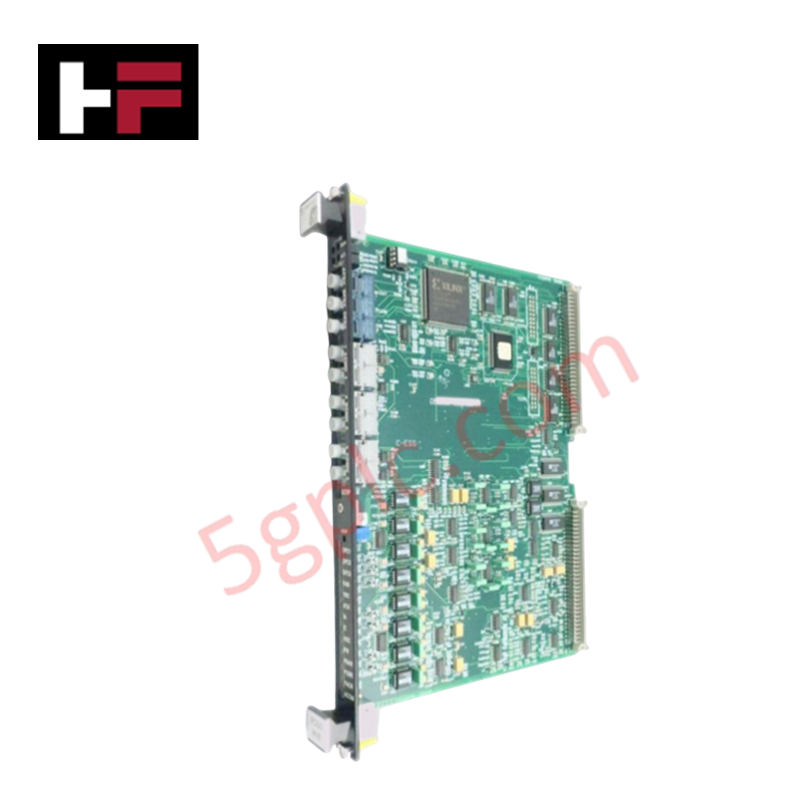
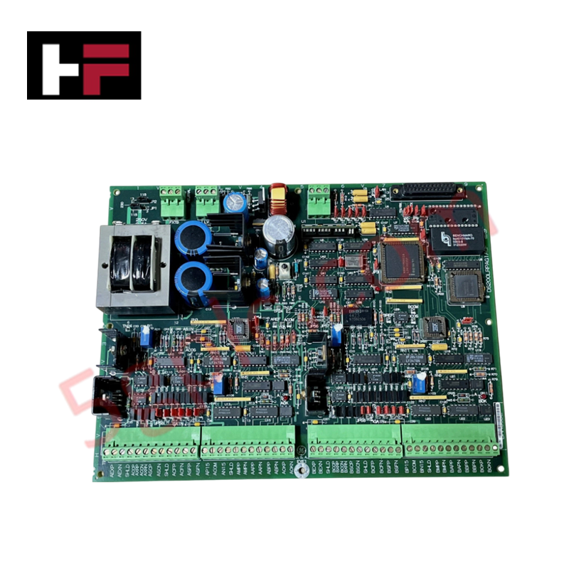
Configured for multi-functional feeder protection and control in electrical distribution networks, the GE F650NFLF2G5HIP6E (F650 Numerical Feeder Protection Relay) provides direct physical/electrical execution of overcurrent, frequency-based tripping, and auto-reclosing logic sequences.
Hardware Specifications
| Parameter | Specification |
|---|---|
| Model | F650NFLF2G5HIP6E |
| Brand | GE Grid Solutions |
| Weight | 2.1 kg |
| Dimensions | 215 x 190 x 115 mm |
| Operating Temp | -20 to 70 deg C |
| Power Consumption | 120/240 VAC/VDC |
| Rated Frequency | 50/60 Hz ±10% |
| Current Inputs | 4 channels (1A or 5A configurable) |
| Voltage Inputs | 4 channels |
Industrial Control Deterministic Network
The F650 integrates into high-speed utility networks supporting protocols including IEC 61850, Modbus, and DNP3. To ensure deterministic data propagation, backplane bus communication velocity must be synchronized with the master substation gateway. The relay utilizes 16 programmable binary inputs and 10 binary outputs for I/O interface, with hardware architecture allowing for firmware flash compatibility to support protocol updates and protection logic revisions. Users must ensure that the communication interface (Ethernet or RS485) is terminated according to protocol specifications to maintain signal integrity and avoid packet latency within the protection bus.
Frequently Asked Questions
Q: Does the F650 support hot-swapping of control modules while the feeder is active?
A: No. Any maintenance involving physical module removal or replacement requires the relay to be isolated and de-energized. Attempting to withdraw the unit while connected to current transformer (CT) secondary circuits will result in high-voltage arcing and loss of protection coverage.
Q: How should the binary I/O be configured to prevent false tripping?
A: Programmable binary inputs must be verified for correct debounce settings in the logic configuration software. Ensure that input circuits are properly shielded and grounded to prevent transient induced noise from being misinterpreted as physical trip signals.
Field Installation Guidelines
- CT Circuit Integrity: Ensure current transformer secondaries are shorted before installation or testing. Permanent damage to CT windings will occur if these circuits remain open-circuited while primary current is flowing.
- Grounding: Terminate the chassis ground stud to the substation earth-ground bar using a minimum 4 mm² copper conductor. Shielded twisted-pair cables should be used for RS485 communication to suppress electromagnetic interference (EMI) typical in switchgear environments.
- Physical Mounting: The unit is designed for panel-mounting. Ensure the cut-out dimensions are accurate to 215 x 190 mm. Tighten mounting hardware uniformly to ensure the gasket provides the intended IP rating against dust and moisture.
- Verification: Prior to commissioning, perform a secondary injection test to confirm the 50/51 overcurrent and 67 directional trip thresholds. Verify the LCD interface displays accurate fundamental phasor values for all voltage and current channels.
Additional Information
- 100% Genuine Parts: All products are original and authentic, ensuring reliable industrial performance.
- 30-Day Refund Guarantee: Return any in-stock item within 30 days in original, unopened packaging for a full refund (excluding shipping and fees).
- 12-Month Warranty: Covers defects in materials or workmanship; excludes misuse, normal wear, or unauthorized modifications.
- Worldwide Shipping: We ship via USPS, UPS, FedEx, and DHL. Delivery times vary by country and may be subject to customs or import fees.
- Support & Contact: Technical and warranty assistance is available anytime. Contact us here: Contact.
- Purchase Guidance: Check product specifications and compatibility carefully before ordering to ensure proper application.
Tech & Buying Guide

Essential SCADA Features for Modern IoT-Enabled Industrial Automation
The convergence of traditional SCADA systems with the Industrial Internet of Things (IIoT) has redefined factory automation. Choosing a robust platform requires more than just standard monitoring capabilities. In this era of Industry 4.0, your supervisory system must bridge the gap between legacy control systems and enterprise-level data integration.

Selecting Rockwell Automation Allen-Bradley PLCs for Small and Mid-Sized Applications
Rockwell Automation remains a cornerstone in global industrial automation. Their Allen-Bradley brand provides a comprehensive portfolio of control systems designed to meet diverse production requirements. Choosing the right programmable logic controller (PLC) is critical for system reliability and scalability. This guide analyzes the Micro and Compact Logix families to help you select the optimal solution for small and medium-scale projects.

Strategic Selection: Choosing the Right SCADA Software for Your PLC Project
In industrial automation, the SCADA (Supervisory Control and Data Acquisition) system acts as the bridge between raw machine data and actionable human intelligence. Selecting the incorrect software platform can lead to integration bottlenecks, scalability issues, and excessive long-term maintenance costs. As an automation consultant with 15 years of experience, I have guided many projects through the selection process. Below are the essential criteria for choosing a platform that ensures both performance and longevity.