










Product Details
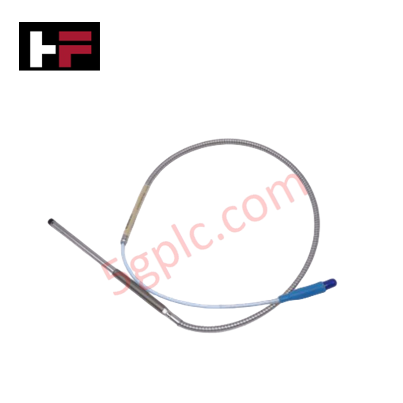
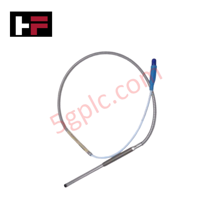
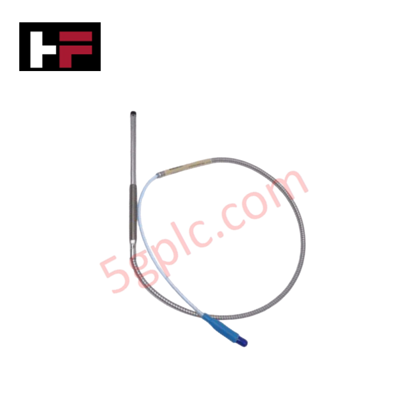
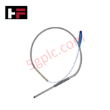
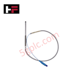
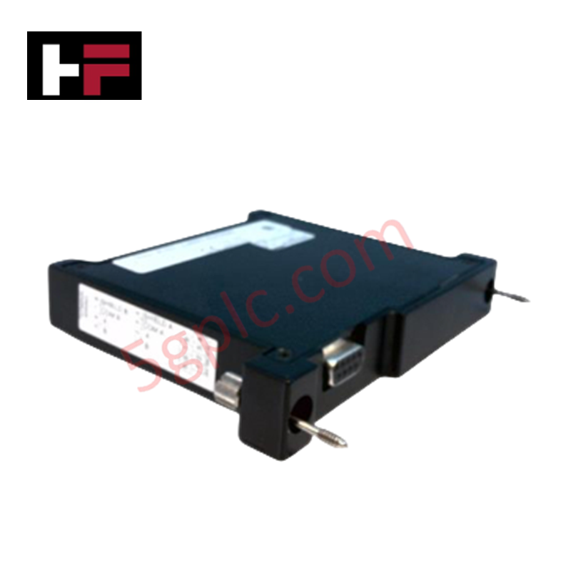
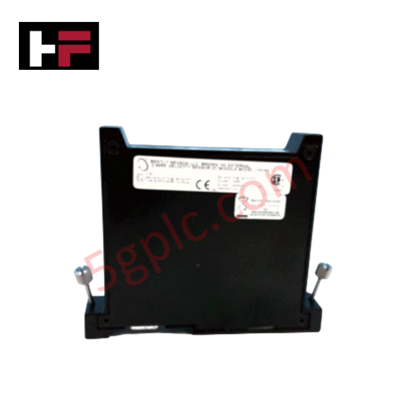
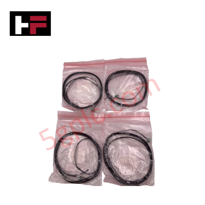
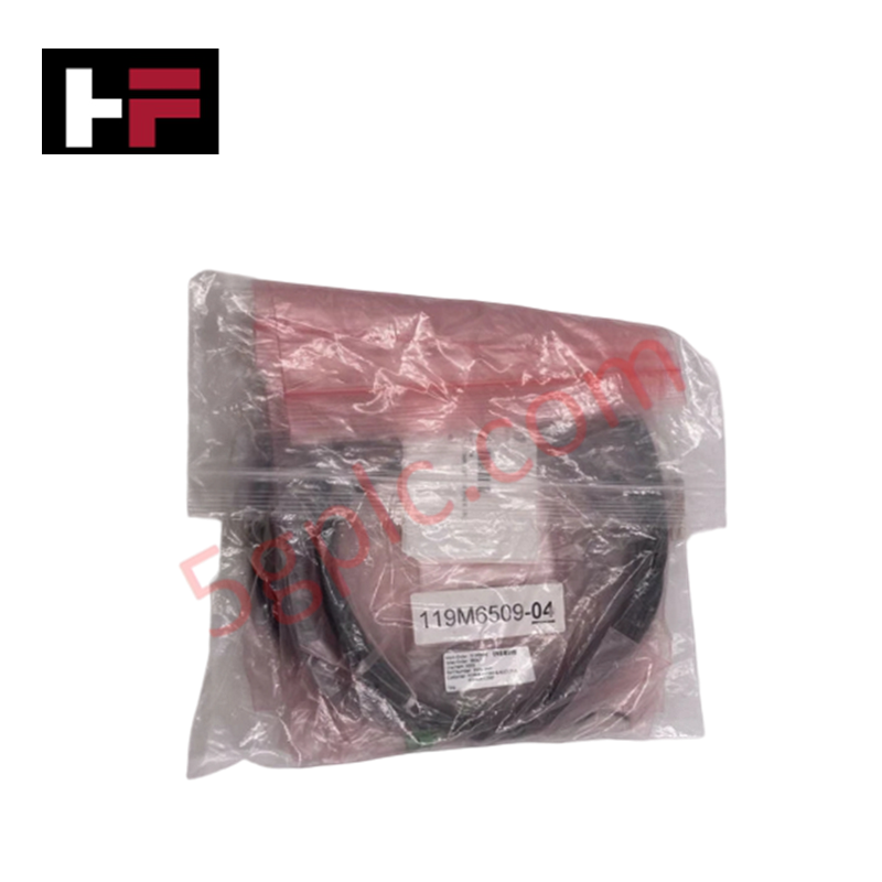
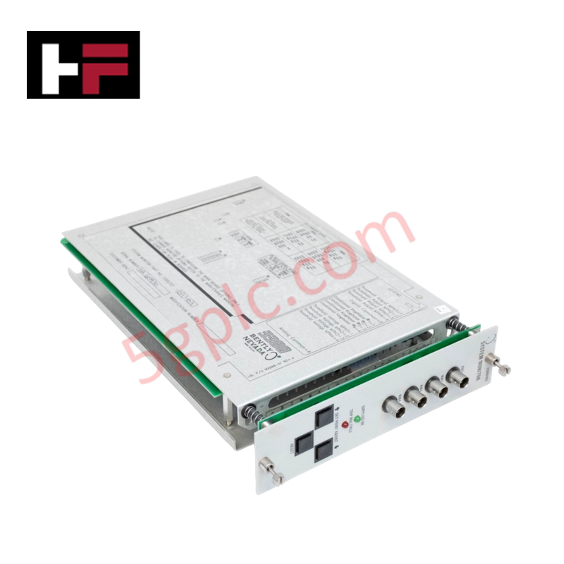
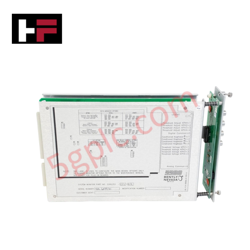
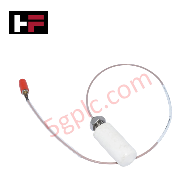
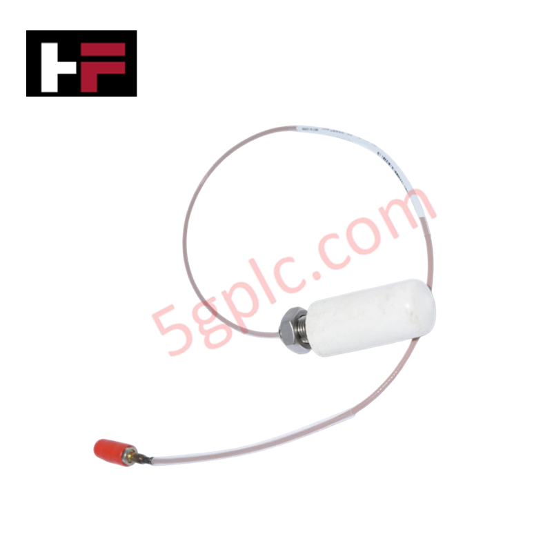
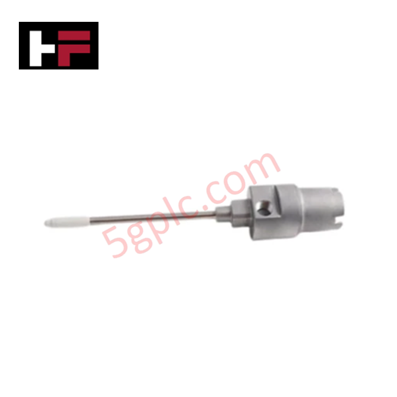
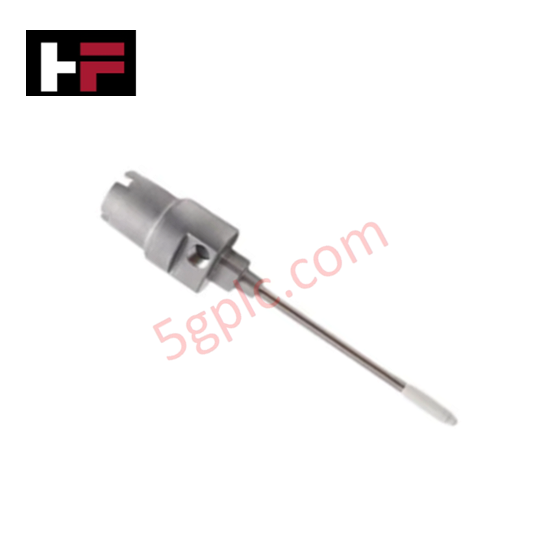
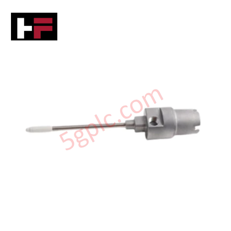
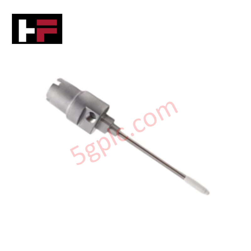
Configured for direct non-contact dynamic vibration and axial position measurement in machinery protection networks, the Bently Nevada 128987-130-01-CN (128987 Proximity Sensor) provides direct physical/electrical execution.
Suffix Breakdown & Model Matrix
| Option Field | Code | Configuration Detail |
|---|---|---|
| Core Model | 128987 | 3300 XL 8 mm proximity sensor transmitter base series |
| Length / Cable Option | 130 | 13.0 in unthreaded / specific casing sleeve configuration |
| Hardware / Fitting | 01 | Standard mounting hardware and connector options |
| Regional Certification | CN | Certified for Chinese market regulatory standards |
Hardware Specifications
| Parameter | Specification |
|---|---|
| Model | 128987-130-01-CN |
| Brand | Bently Nevada |
| Origin | USA |
| Weight | 0.45 kg |
| Dimensions | 33.02 cm x 31.75 cm x 5.08 cm (13.00 in x 12.50 in x 2.00 in) |
| Operating Temp | -40 deg C to +85 deg C |
| Power Consumption | Powered via 10 to 30 VDC loop supply |
| Measuring Range | 0.25 to 1.0 mm |
| Accuracy | +/-0.5% of full scale |
| Repeatability | +/-0.2% of full scale |
| Frequency Response | 0 to 10 kHz |
| Output Signal | 4 to 20 mA loop-powered output |
Eddy-Current Probe Scaling and Gap Voltage Validation
The 128987-130-01-CN integrates high-frequency eddy-current probe scaling to translate mechanical shaft displacement into a proportional 4-20 mA analog output signal. Precision driver electronics process raw vibration and static distance signals across a frequency bandwidth extending from 0 to 10 kHz. Mechanical positioning during startup uses DC gap voltage validation against target -10 VDC baseline equivalents to anchor the probe within its calibrated linear operating window, maximizing signal-to-noise ratios and enabling effective cross-talk suppression between adjacent radial probe channels.
Frequently Asked Questions
Q: How is the 4-20 mA current loop output powered on the 128987-130-01-CN transducer?
A: The sensor operates over a 2-wire loop connection requiring an external power supply voltage between 10 VDC and 30 VDC.
Q: What frequency response limit applies to this transmitter configuration?
A: The internal processing circuitry supports a dynamic frequency response range from static DC up to 10 kHz (-3 dB corner).
Field Installation Guidelines
- Mount the probe assembly into the machine casing port using appropriate NPT or metric thread engagement.
- Connect the loop power supply leads to the 4-20 mA terminal block while maintaining correct polarity.
- Verify target gap distance during static installation by checking loop current or raw voltage to confirm alignment within the linear measuring range.
- Route signal cables through dedicated grounded metal conduit away from high-voltage motor supply lines.
- Ground the cable shield at a single termination point inside the monitoring cabinet to avoid ground loop noise.
Additional Information
- 100% Genuine Parts: All products are original and authentic, ensuring reliable industrial performance.
- 30-Day Refund Guarantee: Return any in-stock item within 30 days in original, unopened packaging for a full refund (excluding shipping and fees).
- 12-Month Warranty: Covers defects in materials or workmanship; excludes misuse, normal wear, or unauthorized modifications.
- Worldwide Shipping: We ship via USPS, UPS, FedEx, and DHL. Delivery times vary by country and may be subject to customs or import fees.
- Support & Contact: Technical and warranty assistance is available anytime. Contact us here: Contact.
- Purchase Guidance: Check product specifications and compatibility carefully before ordering to ensure proper application.
Tech & Buying Guide

Essential Motion Control Commands: A Practical Guide for Engineers
Automation engineers often rely on precise position and speed control to drive modern factory machinery. Modern industrial systems, such as Programmable Logic Controllers (PLCs) and Distributed Control Systems (DCS), depend heavily on standardized motion instructions. Mastering these commands ensures operational safety, protects mechanical components, and optimizes cycle times across production lines.
Mastering Modern Industrial Joystick Controls in Heavy Automation
Industrial joysticks play a pivotal role in human-machine interaction across heavy material handling and mobile hydraulics. These tactile controllers translate complex operator movements into precise electrical signals for PLCs, motion controllers, and DCS networks. Consequently, selecting and installing the right joystick architecture ensures operator safety, reduces fatigue, and optimizes equipment performance.

Navigating Industrial Automation Failures: Types, Causes, and Mitigation Strategies
Modern manufacturing relies heavily on automated control systems to maximize throughput and maintain product quality. However, unplanned downtime in industrial automation can cost facility operators thousands of dollars per hour. Understanding how programmable logic controllers (PLCs), distributed control systems (DCS), and field instrumentation fail empowers engineering teams to implement robust preventive maintenance strategies.