










Product Details
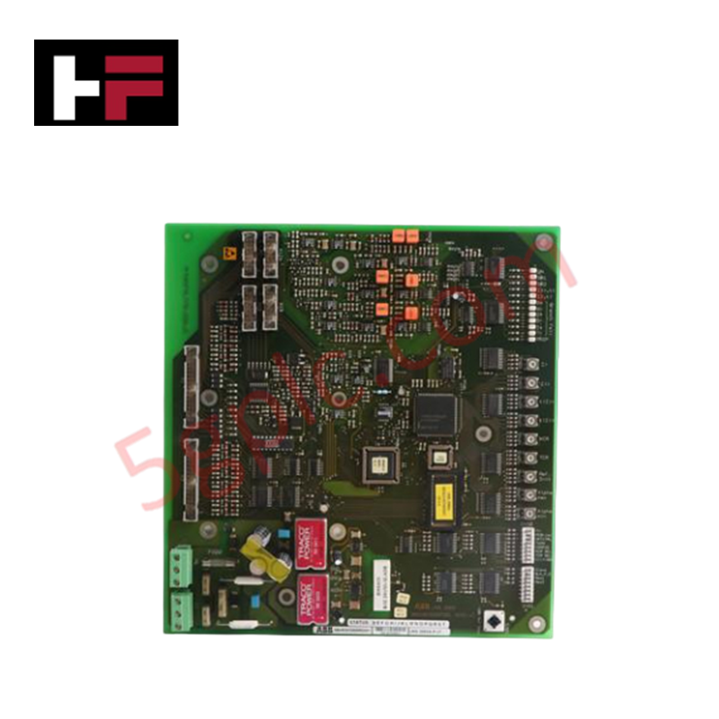
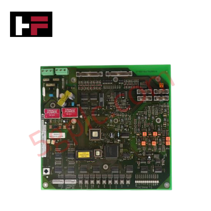
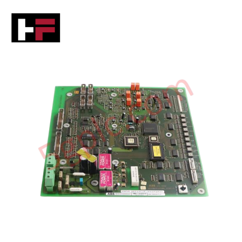
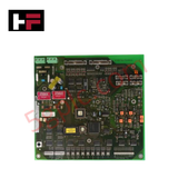
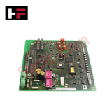
The ABB UNS2882A-P (3BHE003855R0001 Interface Board), also cataloged as the UNS2882A-P,V1 Interface Board, operates as a dedicated hardware component for signal transmission and data communication within industrial control networks.
Hardware Specifications
| Parameter | Specification |
|---|---|
| Model | UNS2882A-P |
| Brand | ABB |
| Part Number | 3BHE003855R0001 |
| Origin | Switzerland |
| Weight | 0.36 kg |
| Dimensions | 255 mm x 240 mm x 35 mm |
| Operating Temp | Standard industrial ambient |
| Power Consumption | System backplane dependent |
Profinet / EtherNet/IP deterministic networks
The UNS2882A-P module manages backplane bus communication velocity to ensure deterministic signal routing between interconnected control nodes. Its internal logic facilitates I/O density scaling, allowing for efficient data handling within high-speed control cycles. Firmware flash compatibility is intrinsically linked to the system's base software revision; engineers must verify the specific V1 revision requirements to ensure seamless integration. The interface board functions by isolating and buffering control signals, preventing bus timing discrepancies and ensuring the integrity of high-priority communication packets across the backplane architecture.
Frequently Asked Questions
Q: Is this interface board capable of hot-swapping while the system is powered?
A: No. Hot-swapping is prohibited. The backplane must be de-energized prior to removing or installing the board to avoid potential damage to the communication pins and integrated circuits caused by transient voltage spikes.
Q: How is the physical address or slot configuration managed for this board?
A: The board is configured via the system engineering software. It must be correctly mapped within the controller hardware scan list to allow for proper data exchange and interrupt prioritization across the backplane.
Field Installation Guidelines
- Mounting: Ensure the board is firmly seated in the rack guide rails. Verify that the backplane connector is fully engaged and that the front-panel mounting screws are tightened to guarantee mechanical stability.
- Grounding: Establish a clean electrical path to the cabinet chassis ground. This is mandatory for mitigating electromagnetic interference (EMI) and maintaining the signal reference levels required for stable bus communication.
- Wiring: Route all communication and I/O cabling through dedicated trays. Maintain physical separation from high-current power cables to minimize inductive coupling and potential data errors.
- Inspection: Prior to installation, conduct a visual check of the gold-plated connector contacts for oxidation or debris. Ensure the PCB surface is free of moisture or conductive contaminants.
- Maintenance: Periodically check that all cable connections are secure and that the surrounding cooling environment allows for adequate thermal dissipation of the module's logic components.
Additional Information
- 100% Genuine Parts: All products are original and authentic, ensuring reliable industrial performance.
- 30-Day Refund Guarantee: Return any in-stock item within 30 days in original, unopened packaging for a full refund (excluding shipping and fees).
- 12-Month Warranty: Covers defects in materials or workmanship; excludes misuse, normal wear, or unauthorized modifications.
- Worldwide Shipping: We ship via USPS, UPS, FedEx, and DHL. Delivery times vary by country and may be subject to customs or import fees.
- Support & Contact: Technical and warranty assistance is available anytime. Contact us here: Contact.
- Purchase Guidance: Check product specifications and compatibility carefully before ordering to ensure proper application.









Tech & Buying Guide

Static UPS vs. Rotary UPS: Technical Evaluation for Industrial Automation

Comprehensive Guide to Noise Types in Industrial Automation and Electronics

Mitigating Emergency Stop Spurious Trips in Industrial Control Systems
Emergency stop (E-Stop) pushbuttons serve as vital safety devices in factory automation and process control plants. Functional safety standards mandate normally-closed (NC) contact blocks to ensure fail-safe operation during wiring breaks or power outages. However, mechanical degradation over time can trigger unexpected spurious trips, halting production lines without an actual emergency. Understanding the underlying causes of mechanical contact failure allows automation engineers to implement robust, fault-tolerant safety circuits.