










Product Details
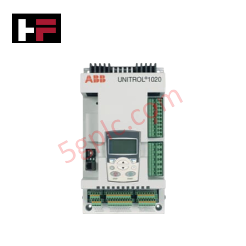
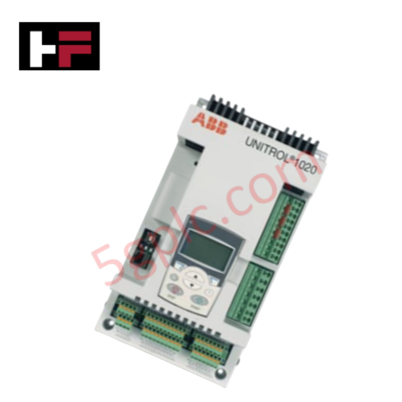
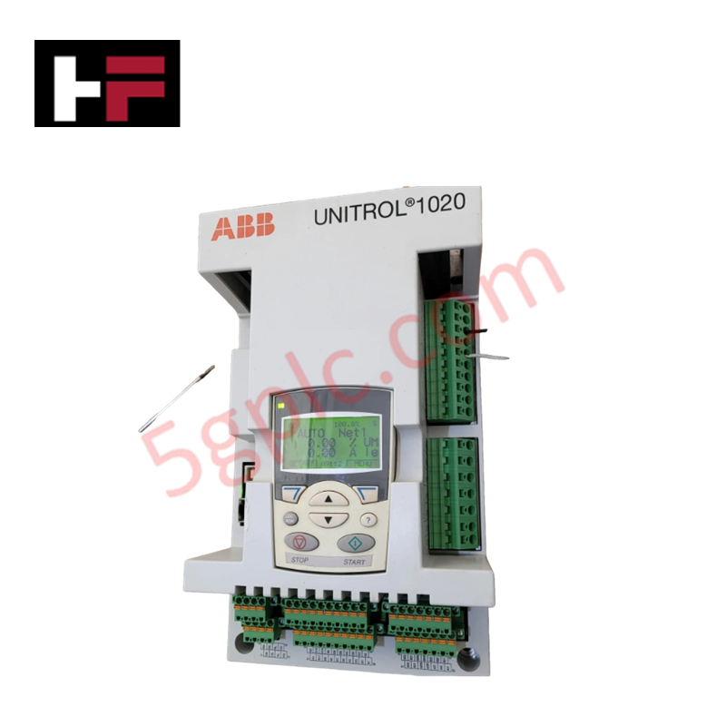
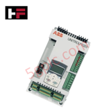
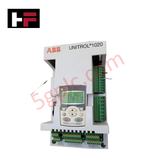
The ABB UNITROL 1020 UNS 0119 A-Z, also cataloged as the UNITROL 1020 Static Excitation Controller, operates as a dedicated hardware component for generator terminal voltage regulation and reactive power control within synchronous generator excitation systems. The hardware samples physical PT/CT voltage and current waveforms to calculate firing angles for downstream thyristor bridges, modulating the direct current injected into the generator field winding. It dynamically loops feedback metrics to execute deterministic terminal corrections under variable stator load changes.
Hardware Specifications
| Parameter | Specification |
|---|---|
| Model | UNITROL 1020 UNS 0119 A-Z 3BHE030579R0003 |
| Brand | ABB |
| Origin | Switzerland |
| Weight | 3.5 kg |
| Dimensions | 88 mm x 483 mm x 200 mm |
| Operating Temp | -25 to +70 deg C |
| Power Consumption | 30 W |
| Power Supply | 24 VDC +/-20% or 110 / 220 VAC |
| Voltage Regulation Accuracy | +/-0.5% |
| Analog Inputs | 4 x 4-20 mA channels |
| Discrete Channels | 6 x digital inputs, 4 x relay outputs |
| Communication Interface | RS485, Ethernet (Modbus RTU/TCP, IEC 61850) |
Profinet / EtherNet/IP Deterministic Networks and Firmware Flash Compatibility
The system communication card interfaces directly with integrated SCADA backplanes via automated protocol maps. For automated substation networks utilizing Profinet / EtherNet/IP deterministic networks, data transmission cycle profiles must be strictly verified against local controller parameters. Field replacement or logic alteration necessitates validation of firmware flash compatibility across all active control microprocessors to prevent timing drops on the synchronous excitation loop, keeping execution response times under the 100 ms limit during grid transients.
Frequently Asked Questions
Q: What are the explicit electrical boundaries governing the hot-swappable maintenance paths of this controller?
A: Hot-swappable maintenance is restricted to peripheral communication cards and user interface segments. The primary terminal block housing the physical PT/CT inputs and the main 24 VDC supply terminal lines must not be disconnected while the synchronous generator is under load to prevent inductive field-discharge faults.
Q: How does the unit process an automatic shift from grid-tied regulation to isolated black start execution?
A: The internal firmware triggers black start sub-routines upon validating a zero-voltage state on the PT inputs while the corresponding discrete input registers an independent flash signal from an auxiliary battery power bank.
Q: What baseline firmware checks are required when networking via the integrated IEC 61850 stack?
A: The flash allocation sector must have the corresponding GSDML or ICD file compilation pre-loaded to match the dataset structure of the remote automation controller, ensuring consistent tag mapping during network reboots.
Field Installation Guidelines
Mount the 2U frame securely within a standard 19-inch electronic rack system that conforms to IP40 or higher protection envelopes. Ensure that the main system ground strap uses a low-impedance copper conductor connected directly to the master copper bus bar of the cabinet. Route all high-voltage PT/CT instrumentation cables within separate, isolated wire tracks, keeping them fully segregated from the low-voltage 4-20 mA analog circuits to eliminate high-frequency cross-talk. Maintain open convective air pathways at the top and bottom vents of the 88 mm chassis to sustain thermal equilibrium across the full -25 to +70 deg C operating scope.
Additional Information
- 100% Genuine Parts: All products are original and authentic, ensuring reliable industrial performance.
- 30-Day Refund Guarantee: Return any in-stock item within 30 days in original, unopened packaging for a full refund (excluding shipping and fees).
- 12-Month Warranty: Covers defects in materials or workmanship; excludes misuse, normal wear, or unauthorized modifications.
- Worldwide Shipping: We ship via USPS, UPS, FedEx, and DHL. Delivery times vary by country and may be subject to customs or import fees.
- Support & Contact: Technical and warranty assistance is available anytime. Contact us here: Contact.
- Purchase Guidance: Check product specifications and compatibility carefully before ordering to ensure proper application.









Tech & Buying Guide

Demystifying CPU Communication Ports in Siemens PLC Architectures
Industrial automation relies heavily on robust data exchange between devices. Without seamless connectivity, field instruments, network switches, human-machine interfaces, and programmable logic controllers cannot coordinate effectively. Therefore, understanding the various CPU communication ports available in Siemens hardware ensures efficient factory automation design and seamless system integration.

Mastering the Siemens PLC Scan Cycle: How the CPU Executes Automation Programs
Industrial automation relies heavily on programmable logic controllers (PLCs) to manage complex manufacturing processes. Many engineers dive straight into programming without mastering the underlying architecture. However, understanding how a PLC CPU executes a program ensures reliable system design. Therefore, mastering the scan cycle optimizes both performance and troubleshooting in modern control systems.

How to Connect to Siemens S7 PLCs: 5 Essential Communication Methods
Establishing a reliable hardware link between a programming terminal and a Siemens SIMATIC controller is essential for engineering workflows. Field engineers rely on distinct physical layers, ranging from legacy serial connections to high-speed Industrial Ethernet protocols. Modern factory automation environments prioritize fast data transfer and seamless driver integration. Selecting the correct connection method simplifies program downloads, online monitoring, and system troubleshooting in complex control systems.