










Product Details
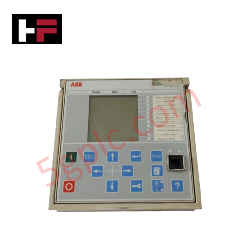
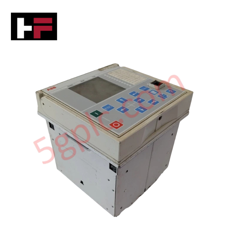
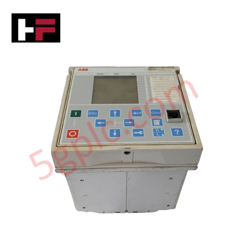
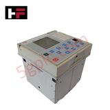
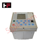
Configured for high-speed thermal overload tracking and phase fault isolation in medium-voltage industrial motor circuits, the ABB REM615E_D (REM615 Motor Protection And Control Relay) provides direct physical/electrical execution. The hardware framework continuously samples multi-channel analog current and voltage inputs at 50/60 Hz to command localized circuit isolation via physical output contacts during rotor anomalies or phase unbalance conditions.
Hardware Specifications
| Parameter | Specification |
|---|---|
| Model | REM615E_D |
| Brand | ABB |
| Origin | Finland |
| Series | Relion 615 Series (REM615) |
| Product Type | Motor protection and control relay |
| Auxiliary Supply Voltage | 48 - 250 V DC / 100 - 240 V AC |
| Frequency | 50/60 Hz |
| Core Protection Scope | Motor thermal overload, stalled motor, frequent starts, phase reversal, unbalance |
| Communication Protocols | IEC 61850, Modbus, DNP3, IEC 60870-5-103 |
| Enclosure Protection | IP54 (Front faceplate panel-mounted) |
| Operating Temp | -25 to +55 deg C |
| Power Consumption | Dependent on active binary output coil excitation and network signaling loads |
| Dimensions | Standard Relion 615 series plug-in unit chassis size |
| Weight | Standard subrack drawout module weight profile |
Profinet / EtherNet/IP Deterministic Networks Performance
To sustain real-time visual monitoring and data logging under critical motor fault states, internal measurement tables route data frames straight into the communication stack. The physical subrack interfaces coordinate time alignment using specific rules that comply with internal backplane bus communication velocity Licences. System modifications that expand input loops utilize standardized I/O density scaling options, which handle multi-protocol parameters. This design requires absolute firmware flash compatibility between peripheral cards and the core CPU to eliminate packet routing latency over IEC 61850 networks.
Frequently Asked Questions
Q: Can the REM615E_D drawout unit be extracted from its plug-in casing while the motor is running?
A: No. Complete unlatching and extraction of the inner protection assembly under active motor load is prohibited. Although the plug-in design features automatic current transformer short-circuiting mechanisms, manual verification of external CT shorting blocks must be completed to ensure safety before physical module removal.
Q: How does the module handle fluctuating auxiliary station power levels?
A: The wide-range internal power circuit accepts inputs between 48 - 250 V DC and 100 - 240 V AC, using internal filtering stages to maintain uninterrupted CPU execution during transient grid voltage dips.
Q: What failure states occur if the network module firmware version deviates from the base unit?
A: A firmware revision mismatch triggers an internal hardware watchdog error, which isolates the backplane communication link, flashes a diagnostic error on the local display, and places the protective output contacts into a safe, deactivated state.
Field Installation Guidelines
- Low-Impedance Frame Bonding: Secure a heavy copper ground strap from the rear casing earth terminal directly to the master panel earth bus. Ensure the mounting surfaces are completely free of non-conductive paint or oxide films.
- Secondary CT Circuit Alignment: Prior to energization, verify that all external current transformer connections match the designated 1 A or 5 A secondary current inputs on the relay terminal matrix.
- Network Run Layout Constraints: Route all communication lines (RJ-45 or optical fiber) through dedicated wire ducts separated from high-voltage alternating current motor supply cabling to avoid induced electromagnetic noise.
Additional Information
- 100% Genuine Parts: All products are original and authentic, ensuring reliable industrial performance.
- 30-Day Refund Guarantee: Return any in-stock item within 30 days in original, unopened packaging for a full refund (excluding shipping and fees).
- 12-Month Warranty: Covers defects in materials or workmanship; excludes misuse, normal wear, or unauthorized modifications.
- Worldwide Shipping: We ship via USPS, UPS, FedEx, and DHL. Delivery times vary by country and may be subject to customs or import fees.
- Support & Contact: Technical and warranty assistance is available anytime. Contact us here: Contact.
- Purchase Guidance: Check product specifications and compatibility carefully before ordering to ensure proper application.









Tech & Buying Guide

Demystifying the DDE Protocol in Legacy Industrial Automation Systems
Modern control systems rely heavily on seamless interprocess communication to exchange operational data between software programs. Microsoft first introduced the Dynamic Data Exchange (DDE) protocol in 1987 to enable real-time data sharing. In factory automation, DDE served as an early bridge between control software and Windows desktop applications. Therefore, understanding DDE mechanics provides crucial insights into how legacy industrial networks established software-level connectivity.

Demystifying CPU Communication Ports in Siemens PLC Architectures
Industrial automation relies heavily on robust data exchange between devices. Without seamless connectivity, field instruments, network switches, human-machine interfaces, and programmable logic controllers cannot coordinate effectively. Therefore, understanding the various CPU communication ports available in Siemens hardware ensures efficient factory automation design and seamless system integration.

Mastering the Siemens PLC Scan Cycle: How the CPU Executes Automation Programs
Industrial automation relies heavily on programmable logic controllers (PLCs) to manage complex manufacturing processes. Many engineers dive straight into programming without mastering the underlying architecture. However, understanding how a PLC CPU executes a program ensures reliable system design. Therefore, mastering the scan cycle optimizes both performance and troubleshooting in modern control systems.