










Product Details
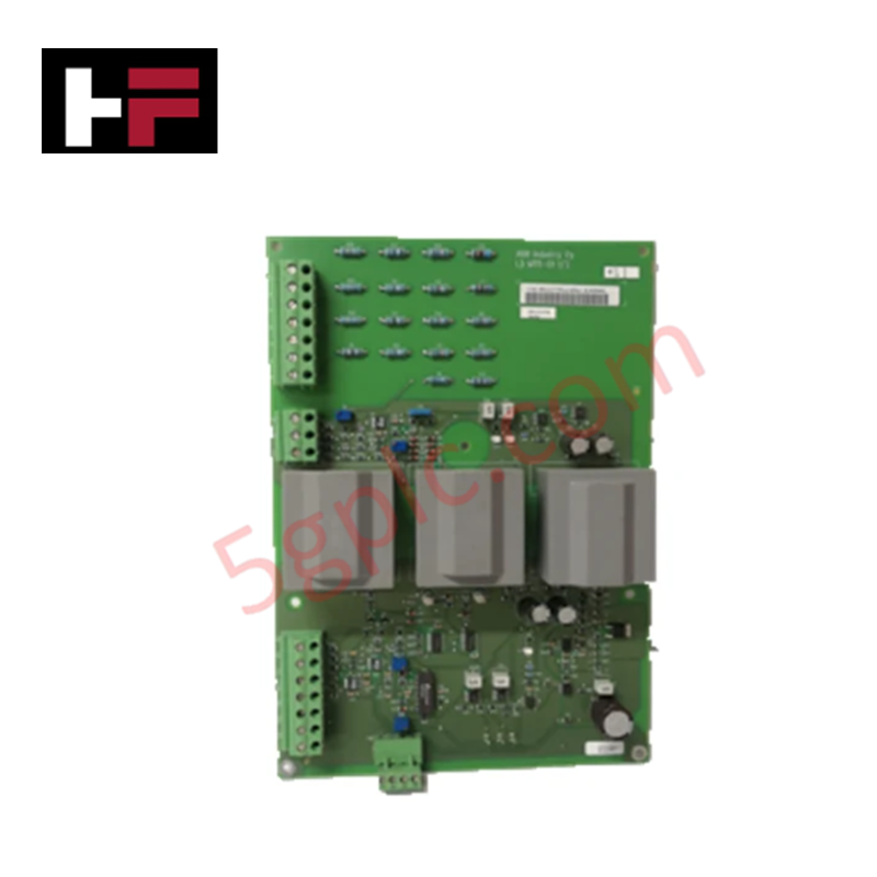
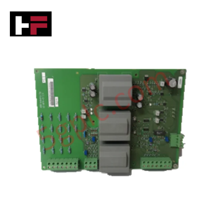
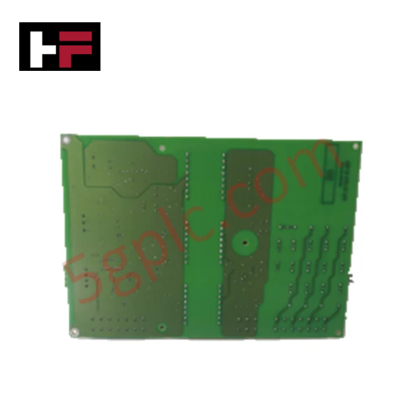
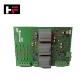
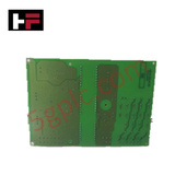
Configured for 16-channel discrete signal execution and field-oriented motor drive control in Modbus TCP/IP networks, the ABB LDMTR-01 63940135F (LDMTR-01 I/O Module) provides direct physical/electrical execution. The unit interfaces brushless DC and BDH motors with Hall sensors and encoders to manage synchronized digital feedback and drive commands.
Hardware Specifications
| Parameter | Specification |
|---|---|
| Model | LDMTR-01 63940135F |
| Brand | ABB |
| Origin | Standard ABB Manufacturing |
| Weight | 1.45 kg |
| Dimensions | 100 mm x 70 mm x 35 mm |
| Operating Temp | -20 to 60 deg C |
| Power Consumption | 24 VDC (Current varies by load application) |
| Input Voltage | 24 VDC |
| Output Voltage | 24 VDC |
| Digital Inputs | 16 channels |
| Digital Outputs | 16 channels |
| Communication Protocol | Modbus TCP/IP |
| Control Modes | Field-oriented control (FOC) |
| Motor Compatibility | Brushless DC and BDH motors with Hall sensors and encoders |
Deterministic Network Bus Integration & Firmware Execution
The module communicates over Modbus TCP/IP networks, utilizing high-speed Ethernet physical layers to execute field-oriented control algorithms without deterministic latency degradation. Embedded memory architectures maintain firmware flash compatibility, allowing deterministic scan updates across 16 input and 16 output channels while interfacing motor Hall sensors and quadrature encoder feedback signals under continuous thermal and electrical stresses.
Frequently Asked Questions
Q: Does the 16-channel I/O stage support external supply voltage isolation?
A: The module relies on a common 24 VDC nominal power rail for internal processing and field output sourcing, requiring proper external fused distribution.
Q: What type of motor feedback signals can be wired directly to the LDMTR-01 module?
A: The module accepts direct interface connections for digital Hall effect sensors and incremental quadrature optical encoders used on brushless DC and BDH motor assemblies.
Field Installation Guidelines
- Ensure the main 24 VDC power source is de-energized prior to connecting or disconnecting terminal blocks and Ethernet interfaces.
- Mount the 100 mm x 70 mm x 35 mm housing on standard DIN rail or enclosure panels using specified torque parameters on mounting hardware.
- Route motor feedback encoder cables separately from high-voltage AC power lines to prevent electromagnetic cross-talk and pulse count errors.
- Verify proper chassis grounding to the system protective earth (PE) bus to ensure noise suppression for the Modbus TCP/IP communication line.
Additional Information
- 100% Genuine Parts: All products are original and authentic, ensuring reliable industrial performance.
- 30-Day Refund Guarantee: Return any in-stock item within 30 days in original, unopened packaging for a full refund (excluding shipping and fees).
- 12-Month Warranty: Covers defects in materials or workmanship; excludes misuse, normal wear, or unauthorized modifications.
- Worldwide Shipping: We ship via USPS, UPS, FedEx, and DHL. Delivery times vary by country and may be subject to customs or import fees.
- Support & Contact: Technical and warranty assistance is available anytime. Contact us here: Contact.
- Purchase Guidance: Check product specifications and compatibility carefully before ordering to ensure proper application.









Tech & Buying Guide

FAT vs SAT in Industrial Control Systems: Key Differences and Execution Guide
Industrial control system deployment relies on strict verification protocols to guarantee operational safety, system stability, and regulatory compliance. Commissioning complex Programmable Logic Controller (PLC) racks, Distributed Control Systems (DCS), and Safety Instrumented Systems (SIS) requires two critical milestones: the Factory Acceptance Test (FAT) and the Site Acceptance Test (SAT). Both procedures validate that system automation meets design specifications, but they occur at different stages of project execution and target distinct operational risks.

Hub vs Switch vs Router in Industrial Automation Architecture
Modern factory automation relies on reliable industrial networking infrastructure to exchange real-time field data across operational technology systems. Engineers often encounter networking hardware like hubs, switches, and routers when integrating Programmable Logic Controllers, Distributed Control Systems, and SCADA monitoring nodes. Although these devices share physical ports, they operate at different layers of the Open Systems Interconnection reference model and deliver distinct traffic management capabilities.

Marshalling Cabinet Preventive Maintenance: Essential Healthiness Checks for PLC, DCS, and ESD Systems
Marshalling cabinets serve as the vital interface between field instrumentation and control room electronics in modern process facilities. Regular preventive maintenance of these cabinets ensures signal integrity across programmable logic controllers (PLCs), distributed control systems (DCS), and emergency shutdown (ESD) networks. System technicians must execute structured inspection protocols to mitigate environmental risks, identify loose wiring, and maintain continuous operational readiness.