













Product Details
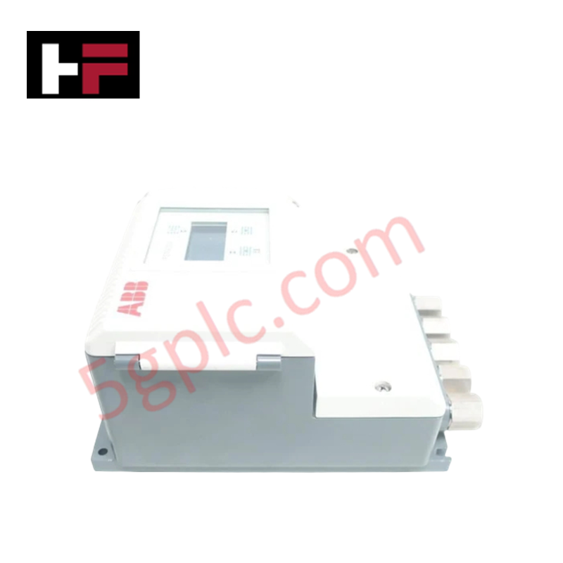
Configured for precise inline conductive liquid flow measurement in industrial process networks, the ABB FSM4000 (FSM4000 Electromagnetic Flowmeter Transmitter) provides direct physical/electrical execution. The hardware processes induced electromotive force signals generated by fluid movement through an applied magnetic field, converting volumetric velocity directly into continuous 4-20 mA current outputs, high-frequency pulse trains, and digital HART communication vectors without moving mechanical parts.
Hardware Specifications
| Parameter | Specification |
|---|---|
| Model | FSM4000 |
| Brand | ABB |
| Nominal Diameter | DN 3 to DN 1000 (1/10 in to 40 in) |
| Process Connection | Flanges per DIN, ASME, or JIS standards |
| Velocity Measurement Range | 0.1 m/s to 10 m/s |
| Measurement Accuracy | Standard: ±0.5% of measured value; Optional: ±0.2% with calibration |
| Operating Temp (Ambient) | -20 deg C to +60 deg C (-4 deg F to +140 deg F) |
| Medium Temperature | -25 deg C to +180 deg C (-13 deg F to +356 deg F) |
| Maximum Process Pressure | Up to 40 bar (580 psi) |
| Power Supply | 85-260 V AC (50/60 Hz) or 20-55 V DC |
| Power Consumption | Max 15 W |
| Signal Outputs | 4-20 mA, pulse, HART protocol |
| Electrode Materials | Stainless steel 1.4571, Hastelloy C, or titanium |
| Liner Materials | PTFE, PFA, or hard rubber |
| Origin | Germany |
| Dimensions | Standard industrial flange pitch dependent on DN size |
| Weight | Nominal size dependent (e.g., approx 7.5 kg for DN 50 rating) |
Backplane Bus Communication Velocity & Protocol Integration
The ABB FSM4000 architecture incorporates deterministic signal conditioning circuits configured to maintain strict communication velocity across HART field networks and integrated bus interfaces. Firmware flash compatibility ensures persistent calibration parameter retention within non-volatile onboard memory during total power interruptions. The internal transmitter processing module executes continuous sensor coil excitation cycles, filtering high-frequency process noise while outputting real-time velocity data to primary DCS controllers with sub-millisecond conversion stability.
Frequently Asked Questions
Q: What is the maximum acceptable loop impedance for the 4-20 mA HART output terminal?
A: The current output loop supports a maximum external load resistance governed by the supply voltage, typically rated up to 750 ohms at standard 24 V DC operating conditions, ensuring signal integrity across long field cabling runs.
Q: How does line noise impact the excitation circuit and output response time?
A: The transmitter utilizes digitally filtered dual-frequency coil excitation. High-frequency noise components are attenuated internally, maintaining an output response time under 100 ms without degrading the ±0.2% calibrated measurement accuracy.
Q: Can the signal converter module be hot-swapped while the field sensor remains under process pressure?
A: The electronic transmitter housing allows field replacement of the processing board assembly provided power is isolated prior to module disconnection. Process pressure within the inline sensor body does not breach the isolated electronic enclosure.
Field Installation Guidelines
Field deployment of the flow transmitter requires adherence to strict mechanical and electrical grounding procedures:
- Straight Run Requirements: Maintain a minimum straight pipe length of 5 pipe diameters (5D) upstream and 3 pipe diameters (3D) downstream from the transmitter flange face to eliminate flow profile turbulence.
- Flange Torque & Alignment: Align mating pipe flanges concentrically. Tighten flange bolts in a cross-pattern sequence to specified torque limits to prevent non-uniform mechanical stress on PTFE/PFA liners.
- Equipotential Grounding: Connect dedicated grounding straps from the sensor housing directly to fluid-contacting grounding rings or adjacent metal flanges. Ensure earth ground impedance remains below 2 ohms to establish a clean zero-voltage reference.
- Cable Shielding: Route 4-20 mA HART and pulse signal wiring in separate grounded metallic conduits away from high-voltage AC motor drives. Terminate cable shields at a single point on the control cabinet side only.
Additional Information
- 100% Genuine Parts: All products are original and authentic, ensuring reliable industrial performance.
- 30-Day Refund Guarantee: Return any in-stock item within 30 days in original, unopened packaging for a full refund (excluding shipping and fees).
- 12-Month Warranty: Covers defects in materials or workmanship; excludes misuse, normal wear, or unauthorized modifications.
- Worldwide Shipping: We ship via USPS, UPS, FedEx, and DHL. Delivery times vary by country and may be subject to customs or import fees.
- Support & Contact: Technical and warranty assistance is available anytime. Contact us here: Contact.
- Purchase Guidance: Check product specifications and compatibility carefully before ordering to ensure proper application.









Tech & Buying Guide

Demystifying the DDE Protocol in Legacy Industrial Automation Systems
Modern control systems rely heavily on seamless interprocess communication to exchange operational data between software programs. Microsoft first introduced the Dynamic Data Exchange (DDE) protocol in 1987 to enable real-time data sharing. In factory automation, DDE served as an early bridge between control software and Windows desktop applications. Therefore, understanding DDE mechanics provides crucial insights into how legacy industrial networks established software-level connectivity.

Demystifying CPU Communication Ports in Siemens PLC Architectures
Industrial automation relies heavily on robust data exchange between devices. Without seamless connectivity, field instruments, network switches, human-machine interfaces, and programmable logic controllers cannot coordinate effectively. Therefore, understanding the various CPU communication ports available in Siemens hardware ensures efficient factory automation design and seamless system integration.

Mastering the Siemens PLC Scan Cycle: How the CPU Executes Automation Programs
Industrial automation relies heavily on programmable logic controllers (PLCs) to manage complex manufacturing processes. Many engineers dive straight into programming without mastering the underlying architecture. However, understanding how a PLC CPU executes a program ensures reliable system design. Therefore, mastering the scan cycle optimizes both performance and troubleshooting in modern control systems.