










Product Details
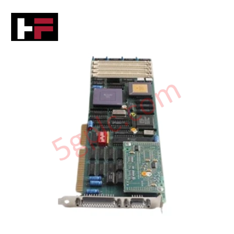
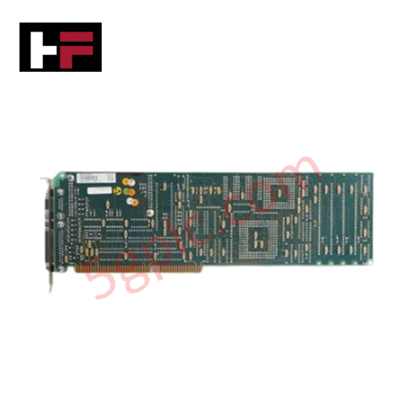
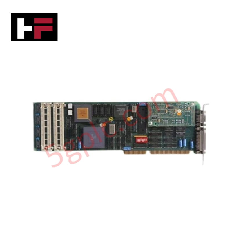
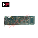
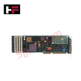
Configured for high-speed signal processing and control bus interfacing in MasterPiece 200 platforms, the ABB DSPU 131 3BSE000355R1 (DSPU 131) Interface Board provides direct physical/electrical execution across system backplane buses.
Hardware Specifications
| Parameter | Specification |
|---|---|
| Model | DSPU 131 |
| Part Number | 3BSE000355R1 |
| Brand | ABB |
| Origin | Sweden / Germany |
| Weight | 0.42 kg |
| Dimensions | Standard MasterPiece rack module dimension |
| Operating Temp | 0 to 55 deg C |
| Power Consumption | System backplane powered |
| Module Type | MA200 Interface Board |
| System Compatibility | MasterPiece 200 (MA200) System Architecture |
| Customs Tariff | 85389091 |
Backplane Bus Communication Velocity & Firmware Flash Compatibility
The DSPU 131 3BSE000355R1 establishes an operational communication link with the MasterPiece 200 backplane, maintaining bus communication velocity for processing high-density system logic routines. Onboard hardware components comply with strict firmware flash compatibility standards to prevent timing drift across backplane bus transactions. Direct bus access allows real-time execution of control algorithms without bottlenecking local signal evaluation circuits.
Frequently Asked Questions
Q: How is the DSPU 131 interface board powered within the rack chassis?
A: Operating power is supplied directly through the system backplane connectors upon insertion into the MasterPiece 200 rack sub-chassis.
Q: Can the DSPU 131 board be inserted or removed while the system backplane is energized?
A: No. Power to the rack rack segment must be isolated prior to board insertion or removal to protect backplane logic lines from voltage transients.
Field Installation Guidelines
- Power Isolation: Disconnect primary power to the rack chassis before inserting or removing the DSPU 131 module to protect backplane pin contacts.
- Static Protection: Wear a grounded ESD wrist strap when handling the board assembly to protect sensitive semiconductor circuitry from electrostatic discharge.
- Card Alignment: Slide the circuit board evenly along the slot card guides until the rear connectors mate securely with the backplane bus socket.
- Mounting Screws: Tighten the front panel retaining screws hand-tight with a screwdriver to ensure earth continuity and mechanical retention under operational vibration.
Additional Information
- 100% Genuine Parts: All products are original and authentic, ensuring reliable industrial performance.
- 30-Day Refund Guarantee: Return any in-stock item within 30 days in original, unopened packaging for a full refund (excluding shipping and fees).
- 12-Month Warranty: Covers defects in materials or workmanship; excludes misuse, normal wear, or unauthorized modifications.
- Worldwide Shipping: We ship via USPS, UPS, FedEx, and DHL. Delivery times vary by country and may be subject to customs or import fees.
- Support & Contact: Technical and warranty assistance is available anytime. Contact us here: Contact.
- Purchase Guidance: Check product specifications and compatibility carefully before ordering to ensure proper application.









Tech & Buying Guide

Marshalling Cabinet Preventive Maintenance: Essential Healthiness Checks for PLC, DCS, and ESD Systems
Marshalling cabinets serve as the vital interface between field instrumentation and control room electronics in modern process facilities. Regular preventive maintenance of these cabinets ensures signal integrity across programmable logic controllers (PLCs), distributed control systems (DCS), and emergency shutdown (ESD) networks. System technicians must execute structured inspection protocols to mitigate environmental risks, identify loose wiring, and maintain continuous operational readiness.

Spatial Computing in Industrial Automation: Elevating PLC and DCS Operations with AR and VR
Industry 4.0 integrates digital intelligence into field operations, transforming factory automation landscapes worldwide. Spatial technologies—specifically Augmented Reality (AR) and Virtual Reality (VR)—redefine how engineers interact with industrial control systems. By bridging computer-generated CAD models with real-time operational technology (OT) data, immersive displays enable intuitive monitoring, rapid diagnostics, and safer maintenance across complex processing facilities.

Master Acceptance Testing: Understanding FAT and SAT in Industrial Control Systems
Factory Acceptance Testing (FAT) and Site Acceptance Testing (SAT) serve as critical quality assurance gateways in complex industrial control systems. Both procedures verify that programmable logic controllers (PLCs), distributed control systems (DCS), and associated field devices meet strict functional specifications. However, executing these tests effectively requires clear delineation between off-site staging and final field commissioning.