












Product Details
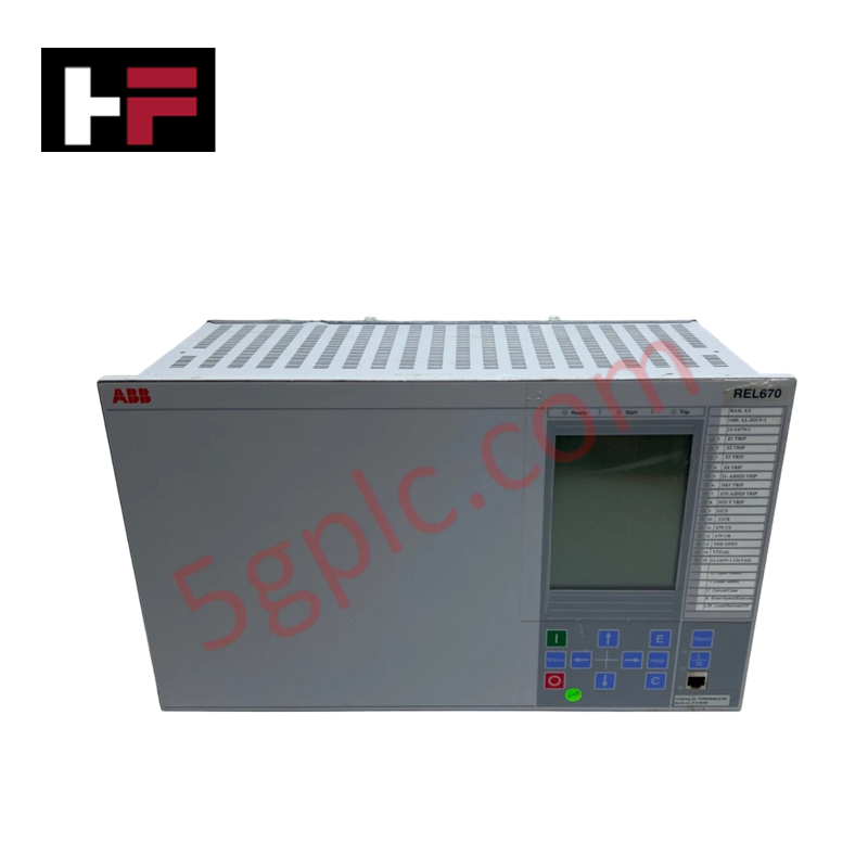
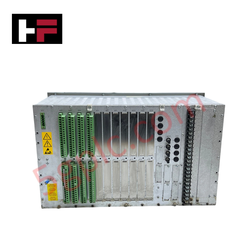
The ABB 1MRK002812-AC, also cataloged as the REL670 Line Distance Protection terminal, operates as a dedicated hardware component for localized control logic execution within substation power transmission systems. Configured for high-speed impedance measurement and selective distance fault isolation across high-voltage transmission networks, this assembly processes phase voltage and current signals to provide direct physical/electrical execution of breakers and trip commands.
Hardware Specifications
| Parameter | Specification |
|---|---|
| Model | REL670 Ver. 1.2 (1MRK002812-AC) |
| Brand | ABB |
| Origin | Sweden |
| Weight | Standard sub-rack protection assembly baseline weight (approx. 5.5 kg) |
| Dimensions | Standard 19-inch rack-mounted casing format |
| Operating Temp | -25 to +55 deg C (Nominal industrial execution range) |
| Power Consumption | Substation battery bank auxiliary powered (24-250 VDC nominal range) |
| Product Type | Line Distance Protection Terminals |
Profinet / EtherNet/IP Deterministic Networks and Firmware Flash Compatibility
The calculation rate of the fault-detection logic loop inside the ABB 1MRK002812-AC matches design-specified internal backplane bus communication velocity constraints. When linking grid measurement parameters over station-level networks or upper communication links utilizing Profinet or EtherNet/IP deterministic networks, the hardware logs events with millisecond timestamp resolution without packet dropping. The protection structure is designed to function smoothly through severe system expansion phases involving aggressive I/O density scaling, provided all added analog sub-cards maintain absolute synchronization with the main chassis firmware flash compatibility registers.
Frequently Asked Questions
Q: Can the internal power supply or analog measurement boards of the REL670 be extracted or serviced via hot-swap methods while the system is under load?
A: No. The line distance protection assembly does not support hot-swap insertion or extraction while energized. Isolating modules under active states can interrupt secondary current transformer paths, causing high-voltage inductive arcing, complete terminal block breakdown, and permanent physical trace damage.
Q: How is a firmware flash compatibility warning managed when swapping a faulty processing module?
A: Hardware revision and software parameters must be verified prior to slot entry using the system terminal calibration tool. An unauthorized mismatch between module sub-assemblies halts initialization to prevent erroneous relay pickup sequences or random contact actuation.
Field Installation Guidelines
- ESD Grounding Protection: Maintenance engineers must wear a properly adjusted and grounded electrostatic discharge (ESD) wrist strap prior to opening the internal terminal structure or handling option slots to prevent micro-circuit failure.
- Current Transformer Termination Sequence: Ensure all secondary current transformer circuits are physically shorted through external shorting bars before connecting any terminal wiring leads to the analog input block.
- Signal Conduit Separation Rules: Route all network fiber-optic leads and low-voltage digital signaling lines through separate shielded wireways. Maintain a minimum separation of 100 mm from high-voltage primary AC power routing paths to reject cross-talk and inductive noise.
- Enclosure Gasket Compression: Mount the terminal assembly flush against the panel rack framework. Torque all front retention studs to establish complete grounding contact and seal the panel face to standard industrial limits against dust intrusion.
Additional Information
- 100% Genuine Parts: All products are original and authentic, ensuring reliable industrial performance.
- 30-Day Refund Guarantee: Return any in-stock item within 30 days in original, unopened packaging for a full refund (excluding shipping and fees).
- 12-Month Warranty: Covers defects in materials or workmanship; excludes misuse, normal wear, or unauthorized modifications.
- Worldwide Shipping: We ship via USPS, UPS, FedEx, and DHL. Delivery times vary by country and may be subject to customs or import fees.
- Support & Contact: Technical and warranty assistance is available anytime. Contact us here: Contact.
- Purchase Guidance: Check product specifications and compatibility carefully before ordering to ensure proper application.









Tech & Buying Guide

Demystifying the DDE Protocol in Legacy Industrial Automation Systems
Modern control systems rely heavily on seamless interprocess communication to exchange operational data between software programs. Microsoft first introduced the Dynamic Data Exchange (DDE) protocol in 1987 to enable real-time data sharing. In factory automation, DDE served as an early bridge between control software and Windows desktop applications. Therefore, understanding DDE mechanics provides crucial insights into how legacy industrial networks established software-level connectivity.

Demystifying CPU Communication Ports in Siemens PLC Architectures
Industrial automation relies heavily on robust data exchange between devices. Without seamless connectivity, field instruments, network switches, human-machine interfaces, and programmable logic controllers cannot coordinate effectively. Therefore, understanding the various CPU communication ports available in Siemens hardware ensures efficient factory automation design and seamless system integration.

Mastering the Siemens PLC Scan Cycle: How the CPU Executes Automation Programs
Industrial automation relies heavily on programmable logic controllers (PLCs) to manage complex manufacturing processes. Many engineers dive straight into programming without mastering the underlying architecture. However, understanding how a PLC CPU executes a program ensures reliable system design. Therefore, mastering the scan cycle optimizes both performance and troubleshooting in modern control systems.