


Product Details
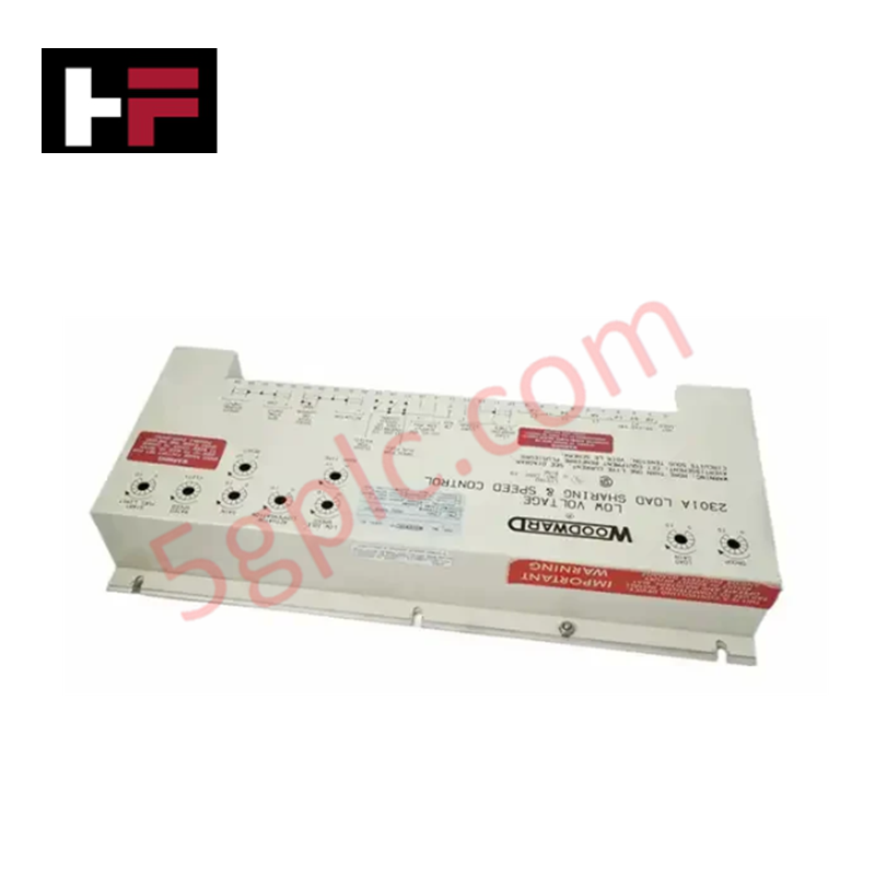
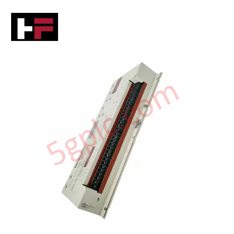
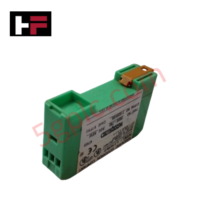
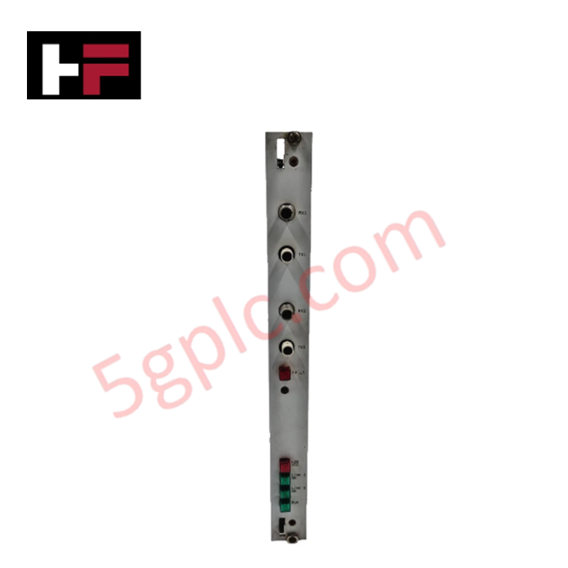
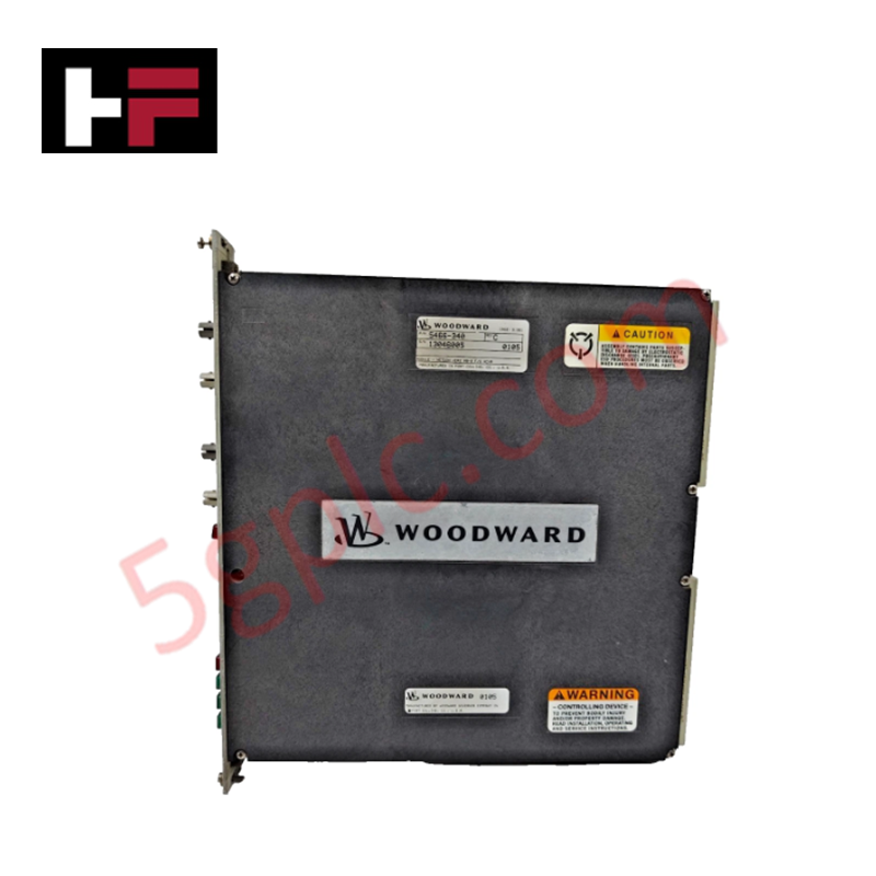
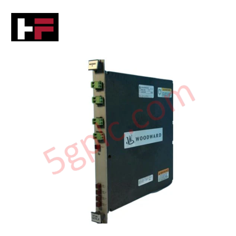
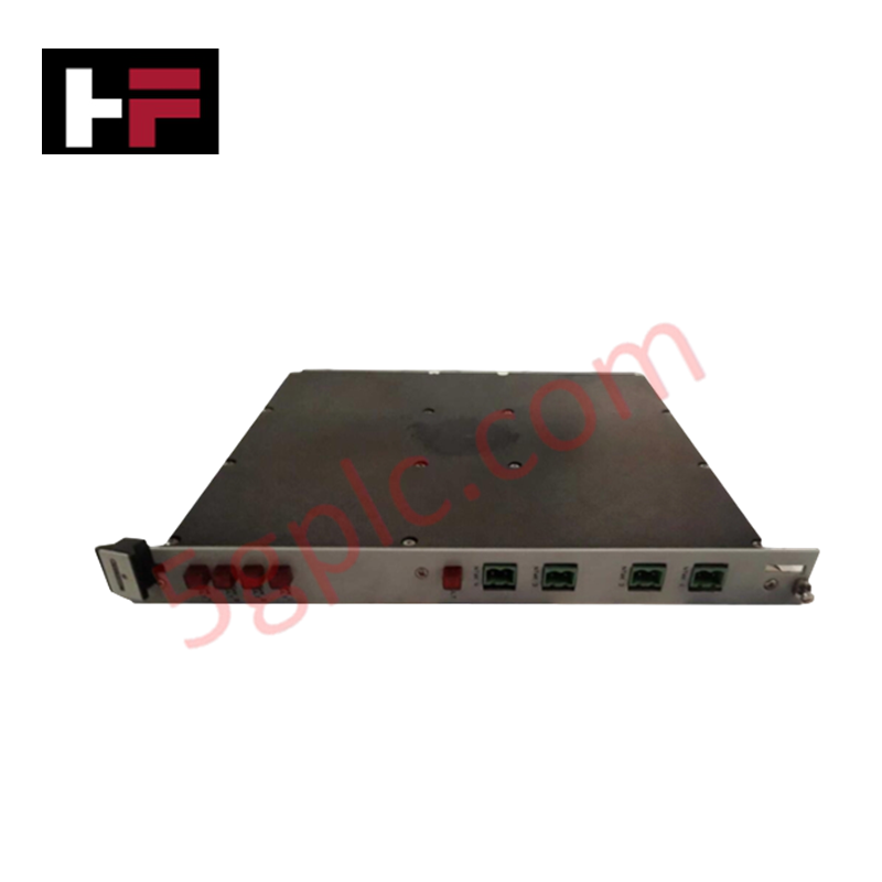
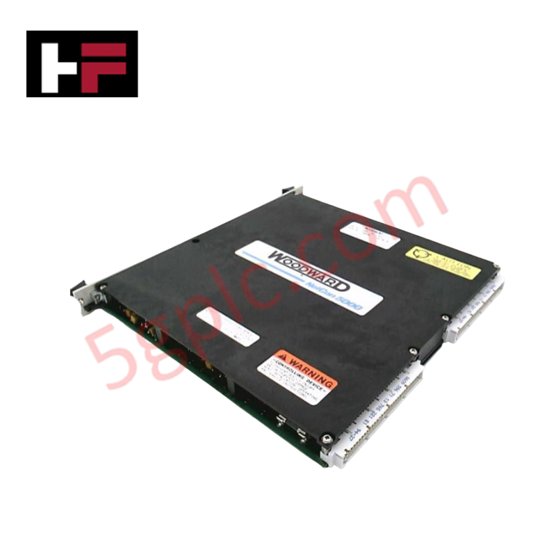
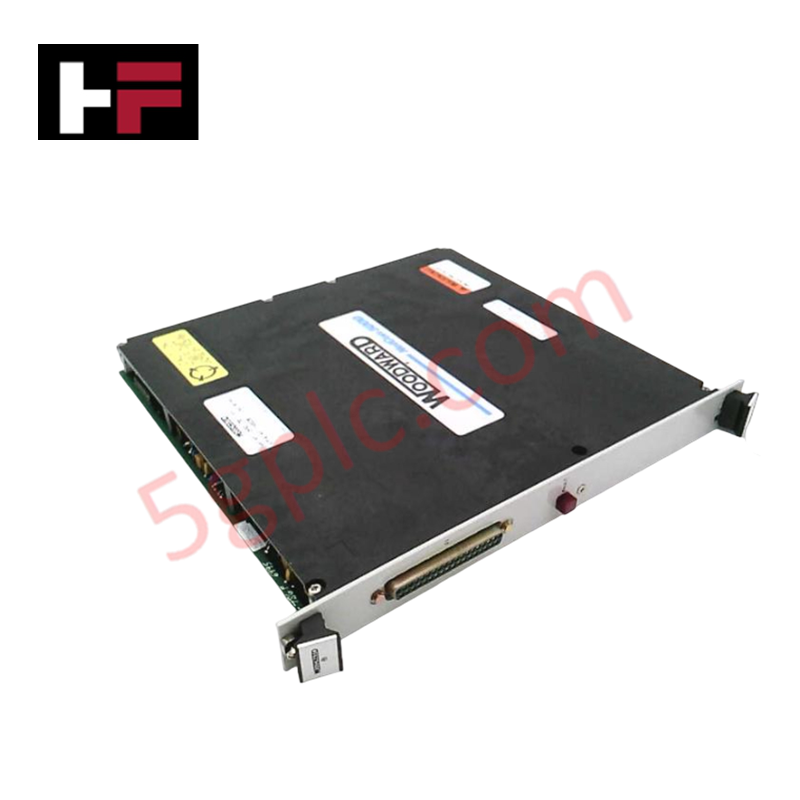
Configured for prime mover load distribution and rotational velocity regulation, the Woodward 9905-068 (9905-068 Load Sharing and Speed Control) provides direct physical/electrical execution of speed sensing and actuator output control within governor systems.
Hardware Specifications
| Parameter | Specification |
|---|---|
| Model | 9905-068 |
| Brand | Woodward |
| Origin | Not specified |
| Weight | < 4 lbs |
| Dimensions | 15.25 x 7.125 x 2.5 in |
| Operating Temp | -40 to 85 deg C |
| Power Consumption | <= 15 W |
| Input Voltage | 20-40 VDC |
| Speed Sensor Input Impedance | 100-300 Ohm |
Actuator Loop Feedback Response
The 9905-068 2301A control module modulates the fuel system via a PID-based output stage designed to maintain engine speed setpoints. To ensure a stable actuator loop feedback response, the controller utilizes internal compensation, gain, and reset potentiometers, which allow for site-specific tuning to match the engine's mechanical time constants. If the prime mover fails to achieve rated no-load speed or exhibits hunting behavior during load sharing, these potentiometers must be adjusted to align the controller output with the actuator's physical response. The unit continuously monitors the load signal to facilitate precise synchronization and load sharing in multi-generator applications, requiring correct current transformer phasing for stable operation.
Frequently Asked Questions
Q: What is the procedure for verifying correct phase operation of the load signal?
A: With the prime mover in isochronous mode and not running, load the generator to near-full capacity and measure the voltage between the negative terminal 11 and positive terminal 13. If measurements indicate a phase error, rotate and record voltage/polarity across the three current transformers to verify correction.
Q: How can I optimize the control loop if the engine does not equalize for rated speed?
A: If speed equalization errors occur, verify the control operation and refine the actuator compensation, gain, and reset potentiometer settings. Ensure these adjustments are performed incrementally while observing the governor's response to step-load changes.
Field Installation Guidelines
- Mounting: Secure the control module in an industrial enclosure using the specified mounting dimensions. Ensure the unit is protected from high-humidity and high-vibration environments, maintaining operation within the -40 to 85 deg C range.
- Wiring: Use shielded cabling for speed sensor inputs and load signal connections to prevent electromagnetic interference. Terminate shields at the cabinet ground point to minimize ground loops that could introduce signal instability.
- Power Connection: Connect a regulated 20-40 VDC power supply to the unit. Ensure the power source is capable of delivering consistent current, as fluctuations can degrade the precision of the speed sensing and control output.
- Validation: Prior to initial startup, perform a cold-loop test to verify current transformer phasing and load signal polarities. Ensure the speed sensor impedance (100-300 Ohm) matches the MPU or proximity probe specifications before commissioning the prime mover into parallel operation.
Additional Information
- 100% Genuine Parts: All products are original and authentic, ensuring reliable industrial performance.
- 30-Day Refund Guarantee: Return any in-stock item within 30 days in original, unopened packaging for a full refund (excluding shipping and fees).
- 12-Month Warranty: Covers defects in materials or workmanship; excludes misuse, normal wear, or unauthorized modifications.
- Worldwide Shipping: We ship via USPS, UPS, FedEx, and DHL. Delivery times vary by country and may be subject to customs or import fees.
- Support & Contact: Technical and warranty assistance is available anytime. Contact us here: Contact.
- Purchase Guidance: Check product specifications and compatibility carefully before ordering to ensure proper application.


Tech & Buying Guide

Strategic Selection: Choosing the Right SCADA Software for Your PLC Project
In industrial automation, the SCADA (Supervisory Control and Data Acquisition) system acts as the bridge between raw machine data and actionable human intelligence. Selecting the incorrect software platform can lead to integration bottlenecks, scalability issues, and excessive long-term maintenance costs. As an automation consultant with 15 years of experience, I have guided many projects through the selection process. Below are the essential criteria for choosing a platform that ensures both performance and longevity.

Ensuring Operational Continuity: The Strategic Value of Redundant Automation Systems
In modern industrial landscapes, unplanned downtime is the ultimate adversary. For sectors relying on complex PLC and DCS architectures, a single hardware failure can trigger catastrophic production losses. Therefore, implementing redundant automation systems is no longer a luxury; it is a fundamental requirement for mission-critical operations. In this article, I analyze why redundancy remains the backbone of reliable industrial infrastructure.

Selecting the Right Cables for Industrial Automation: A Comprehensive Guide
Selecting the appropriate cabling infrastructure is critical for the success of any industrial automation project. Improper cable selection often leads to signal degradation, system instability, and costly downtime. As an automation engineer, I frequently see projects compromised by poor cabling choices in harsh industrial environments. This guide simplifies the complex landscape of cabling to help you make informed decisions for your PLC, DCS, and control systems.