
Product Details
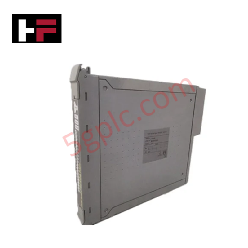
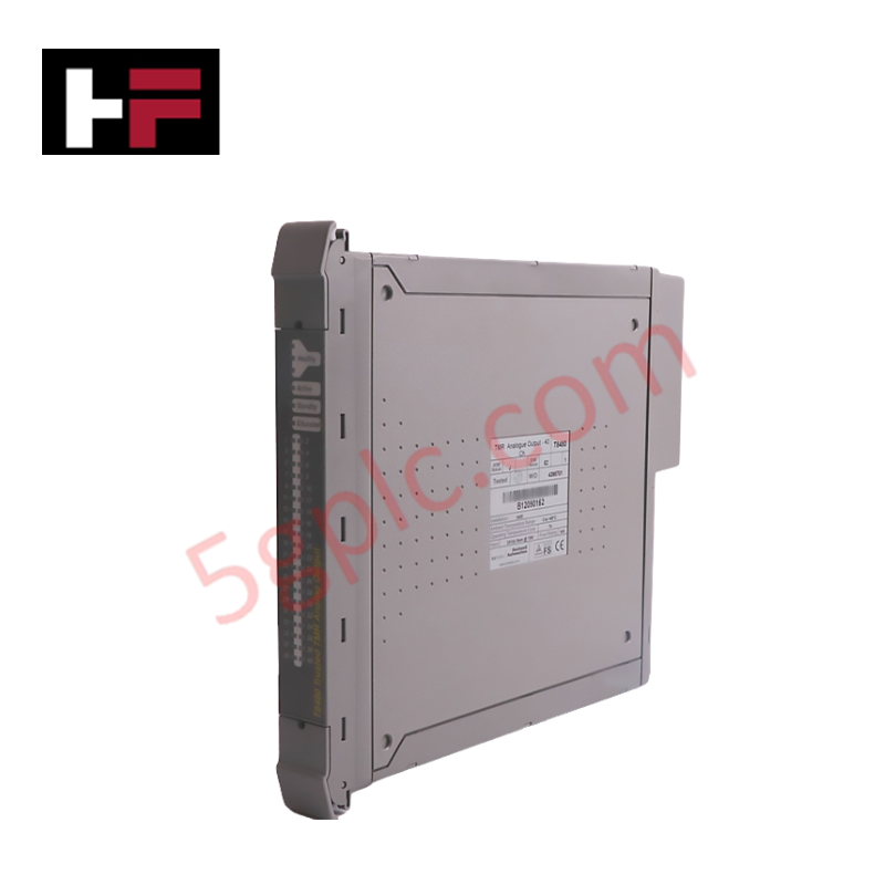
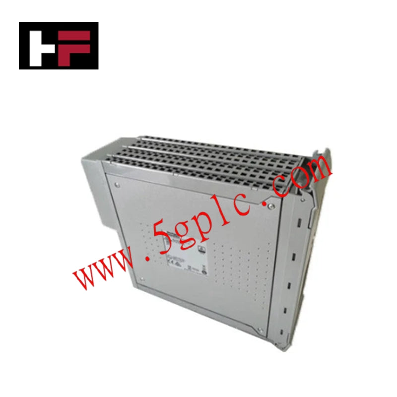
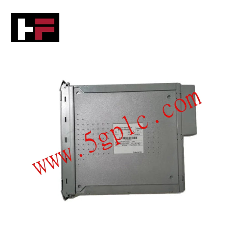
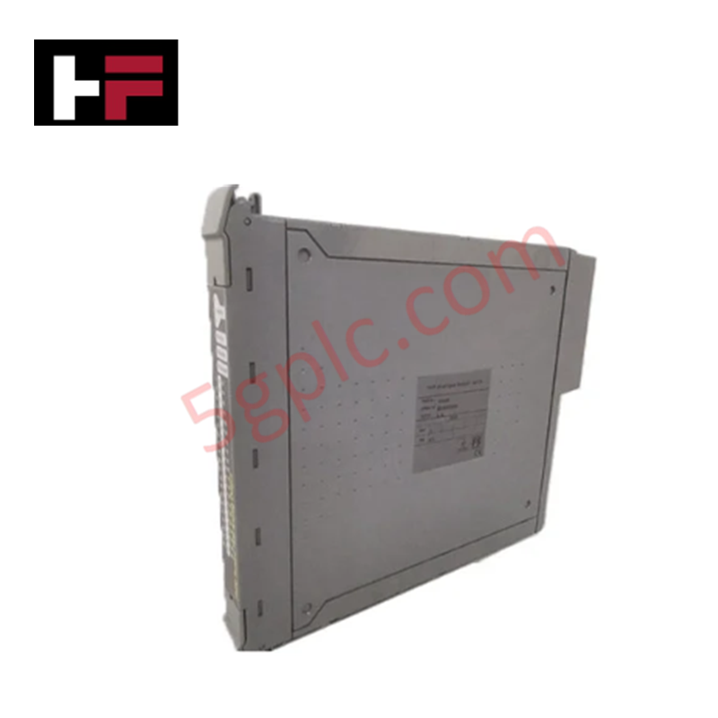
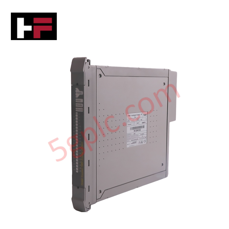
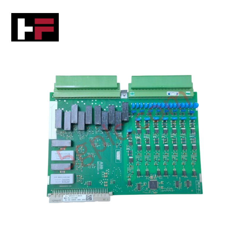
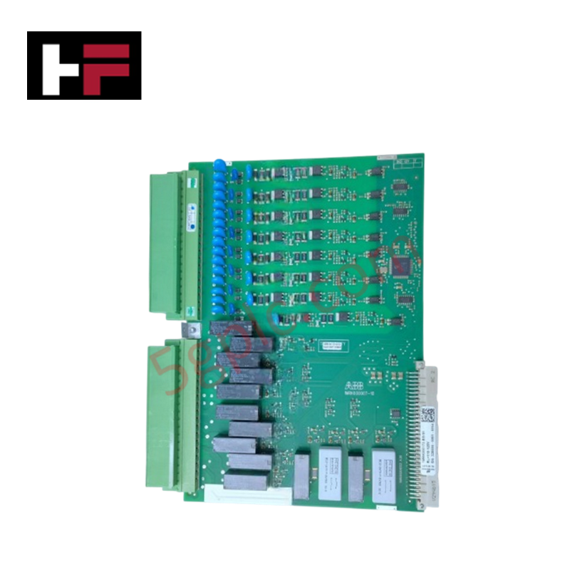
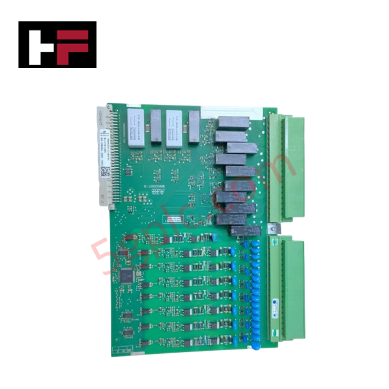
The ABB 1MRK000173-BEr01, also cataloged as the 1MRK000173-BE Binary Input/Output Module, operates as a dedicated hardware component for discrete signal acquisition and trip circuit command routing within ABB REx670 V1.1 protection relay systems.
Hardware Specifications
| Parameter | Specification |
|---|---|
| Model | 1MRK000173-BEr01 |
| Brand | ABB |
| Origin | Standard ABB Manufacturing |
| Weight | 0.47 kg |
| Dimensions | Standard Relion 670 Card Slot |
| Operating Temp | -25 to +70 deg C |
| Power Consumption | 110-125 VDC (50 mA Rated Loop Current) |
| Binary Inputs | 8 Discrete Channels |
| Relay Outputs | 10+2 Contact Channels |
| Switching Time | <10 ms |
| Contact Resistance | <50 mOhm |
Deterministic Networks & Backplane Communication
The module processes field status transitions through 8 discrete input channels while triggering 10+2 relay contact outputs with switching response times under 10 ms. High-speed backplane bus communication velocity allows immediate transmission of event records and status changes to the main processing unit. Firmware flash compatibility across the REx670 platform ensures synchronization over deterministic IEC 61850 networks without introducing backplane latency.
Frequently Asked Questions
Q: What is the nominal operating voltage for the discrete binary input loops on this module?
A: The module is rated for 110-125 VDC system loops with a nominal operating current of 50 mA.
Q: What are the electrical and mechanical contact endurance ratings for the output relays?
A: Output contact relays provide a mechanical durability of 10 million operations and an electrical switching endurance of 100,000 operations at rated electrical load.
Field Installation Guidelines
- Ensure the host REx670 enclosure is fully powered down before inserting or reseating the module in the chassis slot.
- Route auxiliary DC power lines and contact output cables through grounded metallic conduits to minimize electromagnetic interference.
- Maintain loop wiring within specified voltage ranges (110-125 VDC) to prevent damage to internal optocoupler sensing circuits.
- Secure all terminal block retention screws to ensure stable physical contact resistance under continuous vibration.
Additional Information
- 100% Genuine Parts: All products are original and authentic, ensuring reliable industrial performance.
- 30-Day Refund Guarantee: Return any in-stock item within 30 days in original, unopened packaging for a full refund (excluding shipping and fees).
- 12-Month Warranty: Covers defects in materials or workmanship; excludes misuse, normal wear, or unauthorized modifications.
- Worldwide Shipping: We ship via USPS, UPS, FedEx, and DHL. Delivery times vary by country and may be subject to customs or import fees.
- Support & Contact: Technical and warranty assistance is available anytime. Contact us here: Contact.
- Purchase Guidance: Check product specifications and compatibility carefully before ordering to ensure proper application.






Tech & Buying Guide

Understanding VFD Mechanical Brake Logic and Control in Industrial Automation
Variable Frequency Drives (VFDs) play a crucial role in modern industrial automation by controlling motor speed, torque, and acceleration. However, high-inertia loads and vertical lifting systems require precise mechanical braking logic to ensure operational safety and prevent equipment damage.

Why Programmable Logic Controllers Drop into Stop Mode: An Expert Analysis
Industrial automation systems rely heavily on Programmable Logic Controllers (PLCs) to maintain uninterrupted production. When a PLC unexpectedly shifts from Run to Stop mode, whole manufacturing lines stall.
As control systems evolve across modern factory automation, understanding the root causes of these interruptions helps engineers minimize costly downtime. This technical guide breaks down why PLCs trip into Stop mode and provides practical strategies to mitigate system faults.

Understanding Root Causes of Unplanned PLC Stop Mode in Industrial Automation
Modern Programmable Logic Controllers manage execution through distinct operational states: Run, Stop, Start-Up, and Hold. During power-up, a controller initializes memory registers within Stop mode before briefly transitioning to Start-Up mode. During this phase, internal self-diagnostics evaluate system integrity across hardware and user programs. If the controller detects no critical faults, it enters Run mode to execute the control program continuously. However, any severe system anomaly forces the CPU back into Stop mode immediately to prevent erratic machine behavior across the plant floor.