


Product Details
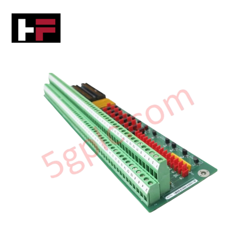
Configured for signal interface within Mark V Speedtronic systems, the GE DS200TBCBG1AAA (DS200TBCB Input Termination Module) provides direct physical execution for RTD and current loop sensor landing.
Hardware Specifications
| Parameter | Specification |
|---|---|
| Model | DS200TBCBG1AAA |
| Brand | General Electric |
| Origin | USA |
| Power Consumption | +5 V DC, 6 A |
| Core Function | RTD and 4-20 mA signal termination |
Industrial Control & Firmware Compatibility
The DS200TBCBG1AAA operates as a passive interface board, facilitating I/O density scaling by routing temperature and process current signals to the TCCB board within the core. Deterministic signal transmission is achieved through a fixed hardware architecture; the module does not require firmware, thereby avoiding firmware flash compatibility requirements. Eight of the input channels support hardware-level reconfiguration via jumpers to switch from 4-20 mA to 0-1 mA signal ranges. Signal integrity is maintained through integrated termination logic that interfaces directly with the backplane bus, ensuring that converted sensor data is correctly mapped to the system's control processors.
Frequently Asked Questions
Q: Can the input range be modified for specific channels?
A: Yes. Eight of the 4-20 mA input channels feature hardware jumpers that allow for reconfiguration to support 0-1 mA input signals. This physical adjustment must be made at the board level.
Q: Is this module hot-swappable during system operation?
A: No. The TBCB module must be de-energized before removal or installation. Ensure that all power is removed from the associated core and terminal blocks to prevent damage to the module circuitry or accidental disruption of the control loops.
Field Installation Guidelines
- Signal Routing: Ensure all RTD and mA sensor leads are landed securely on the terminal blocks. Verify signal polarity for 4-20 mA loops to prevent open-circuit or reversed-polarity conditions.
- Jumper Configuration: If using the 0-1 mA input range, verify that the corresponding jumpers are correctly set before energizing the module. Improper jumper settings may lead to signal reading errors at the controller level.
- Grounding and Shielding: Terminate sensor cable shields at the designated chassis ground points. Maintaining a low-impedance ground reference is necessary to minimize common-mode noise on the sensitive RTD temperature measurement circuits.
- Cabinet Integration: Mount the module in location seven of the core assembly. Ensure proper alignment with the backplane connector to avoid pin deformation during insertion.
Additional Information
- 100% Genuine Parts: All products are original and authentic, ensuring reliable industrial performance.
- 30-Day Refund Guarantee: Return any in-stock item within 30 days in original, unopened packaging for a full refund (excluding shipping and fees).
- 12-Month Warranty: Covers defects in materials or workmanship; excludes misuse, normal wear, or unauthorized modifications.
- Worldwide Shipping: We ship via USPS, UPS, FedEx, and DHL. Delivery times vary by country and may be subject to customs or import fees.
- Support & Contact: Technical and warranty assistance is available anytime. Contact us here: Contact.
- Purchase Guidance: Check product specifications and compatibility carefully before ordering to ensure proper application.


Tech & Buying Guide

Redundant Automation Systems: Ensuring Continuous Uptime in Critical Control Infrastructure
System reliability directly determines operational profitability across high stakes process industries. Modern industrial automation platforms must eliminate single points of failure to prevent catastrophic shutdowns. Deploying fault tolerant architecture safeguards complex facilities against unexpected hardware glitches, network disruptions, and maintenance outages.

Understanding Types of Noise in Electronic Circuits and Control Systems
Signal integrity directly determines measurement accuracy and loop stability across industrial automation environments. Electronic noise introduces unwanted stochastic interference into analog loops, sensor feedback lines, and digital fieldbus networks. Understanding how intrinsic electronic noise and external electromagnetic interference manifest allows control engineers to optimize signal conditioning and shield sensitive instrumentation effectively.

Why 24V DC Power Supplies Standardize Modern Industrial Automation
Industrial control cabinets worldwide rely on 24V DC as the universal power standard for field instrumentation, sensors, and controllers. Walk into any manufacturing plant, and you will find PLCs, human-machine interfaces (HMIs), and smart actuators running on extra-low voltage DC. Standardizing on 24V DC enhances operational safety, lowers cabinet footprint, and maintains steady control performance across factory networks.