








Product Details
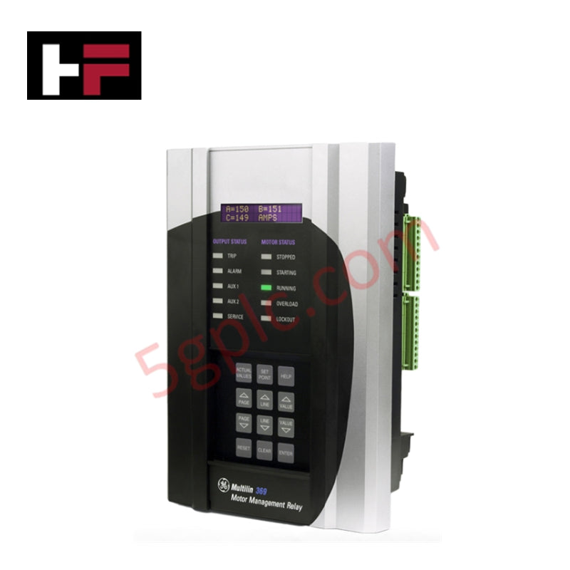
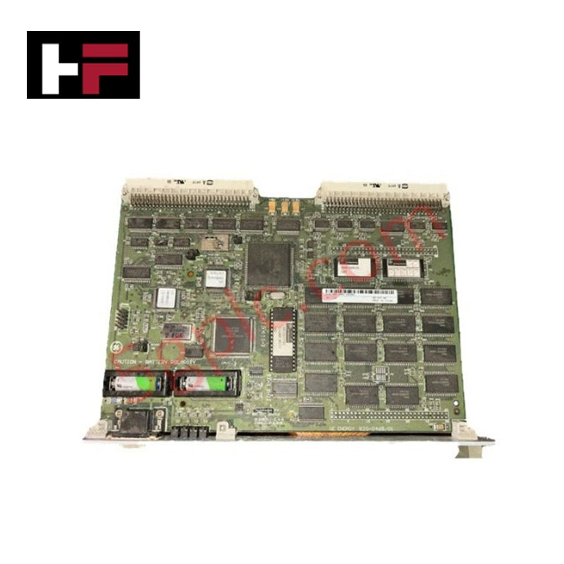
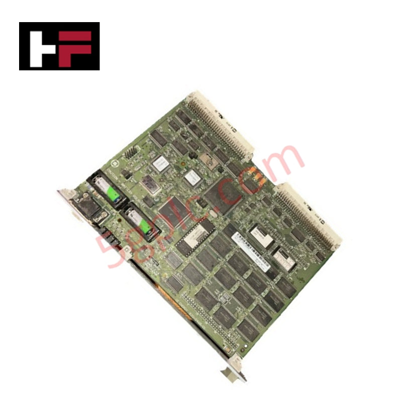
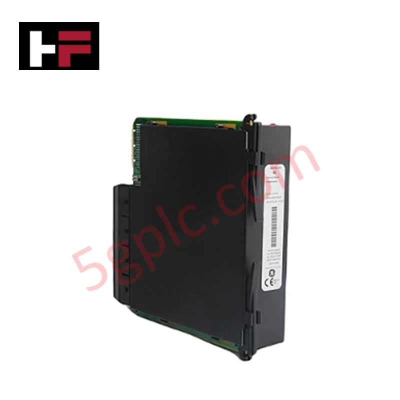
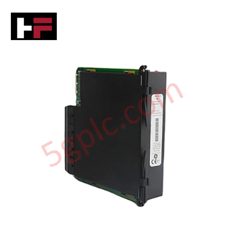
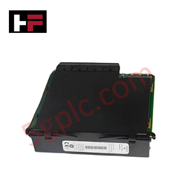
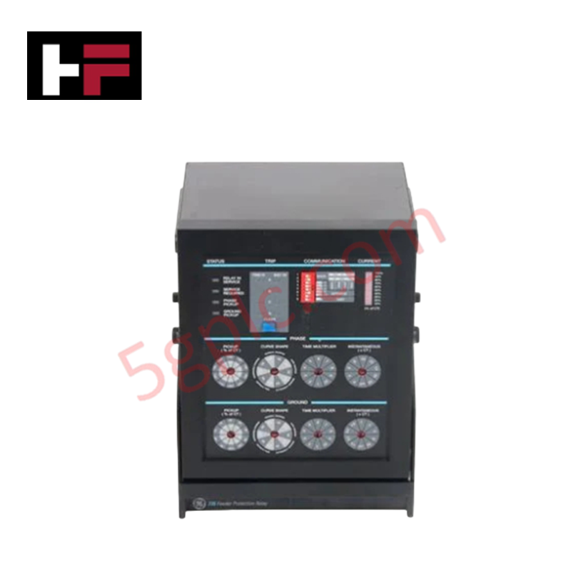
Configured for motor protection and thermal monitoring in industrial control environments, the GE Multilin 369-HI-R-M-0-0 (369 Motor Management Relay) provides direct physical/electrical execution.
Suffix Breakdown & Model Matrix
| Option Code | Description | Functional Range |
|---|---|---|
| 369 | Base Unit | Core relay chassis without base RTD inputs |
| HI | Control Power | 50-300 VDC / 60-265 VAC range |
| R | RTD Configuration | 12 built-in RTD inputs |
| M | Metering Package | Integrated electrical parameter metering |
| 0 | Fiber Optic Port | No optional fiber optic port installed |
| 0 | Protocol Interfaces | No optional protocol interfaces installed |
Hardware Specifications
| Parameter | Specification |
|---|---|
| Model | 369-HI-R-M-0-0 |
| Brand | GE Multilin |
| Origin | USA |
| Control Power Voltage | 50-300 VDC / 60-265 VAC |
| RTD Inputs | 12 built-in channels |
| Integrated Metering | Voltage, current, power, and energy monitoring |
| Net Weight | 4.5 kg |
| Shipping Weight | 5.5 kg |
| Operating Temp | -40 to 60 deg C |
| Power Consumption | 20 W maximum |
| Dimensions | Standard 369 flush mount enclosure |
Backplane Bus Communication & Firmware Flash Compatibility
The relay incorporates integrated firmware processing logic to continuously calculate thermal capacity used and evaluate incoming sensor inputs. Firmware flash compatibility ensures structured data logging across power cycles while supporting determinism during high-current fault evaluations. System memory logic coordinates relay trip outputs and metering registers directly via the internal processing bus.
Frequently Asked Questions
Q: What power source parameters are accepted by the HI control power supply option?
A: The HI power option accepts an operating input range of 50 to 300 VDC or 60 to 265 VAC.
Q: How are motor thermal limits monitored with the R option?
A: Option R provides 12 built-in RTD sensor inputs to directly monitor stator, bearing, and ambient temperature signals for dynamic thermal model calculations.
Q: Can fiber optic interfaces be retrofitted into the 0 port position field units?
A: Option code 0 indicates no fiber optic port hardware is populated on the internal processing board, requiring factory-configured hardware for optical loop operation.
Field Installation Guidelines
- Cut a standard panel cutout and insert the unit from the front, securing it via the provided mounting brackets and side hardware.
- Connect protective earth directly from the panel ground bar to the chassis grounding terminal using a minimum 12 AWG copper conductor.
- Wire the 12 RTD inputs using shielded twisted-pair cables, grounding the shield drain wire at the relay end only to prevent ground loops.
- Separate low-voltage RTD wiring and signal connections from high-voltage control power lines and CT/VT wiring trunks.
- Verify that control supply voltage conforms to the 50-300 VDC / 60-265 VAC limit before energizing the power terminals.
Additional Information
- 100% Genuine Parts: All products are original and authentic, ensuring reliable industrial performance.
- 30-Day Refund Guarantee: Return any in-stock item within 30 days in original, unopened packaging for a full refund (excluding shipping and fees).
- 12-Month Warranty: Covers defects in materials or workmanship; excludes misuse, normal wear, or unauthorized modifications.
- Worldwide Shipping: We ship via USPS, UPS, FedEx, and DHL. Delivery times vary by country and may be subject to customs or import fees.
- Support & Contact: Technical and warranty assistance is available anytime. Contact us here: Contact.
- Purchase Guidance: Check product specifications and compatibility carefully before ordering to ensure proper application.

Tech & Buying Guide
Multi-Touch HMI Technology: Transforming Interaction in Industrial Automation
Modern human-machine interfaces (HMIs) are evolving rapidly across factory floors worldwide. Traditional resistive touchscreens allowed operators to register only a single touch point at a time. Today, multi-touch HMI panels enable intuitive multi-finger gestures and concurrent multi-operator inputs in demanding industrial automation setups.

Centralized vs Decentralized Automation Systems: Architectural Trade-Offs in Modern Industrial Control
Industrial automation relies heavily on robust control architectures to manage complex processes efficiently. Engineers must choose between centralized and decentralized topologies when designing plant automation. This decision directly impacts system reliability, scalability, and long-term maintenance costs.

Engineering a Process Control System Philosophy: Principles and Operational Impact
A Process Control System (PCS) Philosophy serves as the foundational blueprint for modern plant engineering. During the design and construction phases, this document establishes clear guidelines for instrumentation and control (I&C) teams. Consequently, a well-defined philosophy directly dictates overall operational stability, maintenance efficiency, and future expansion capabilities across heavy process industries.