











Product Details
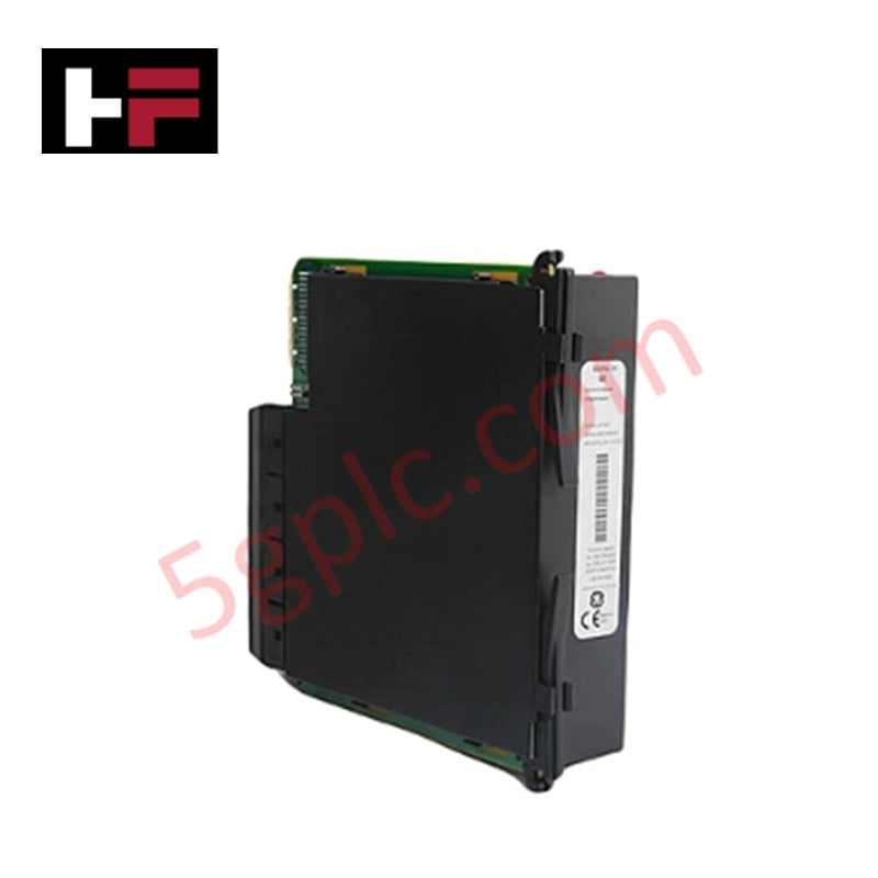
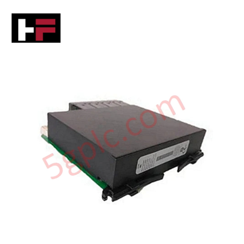
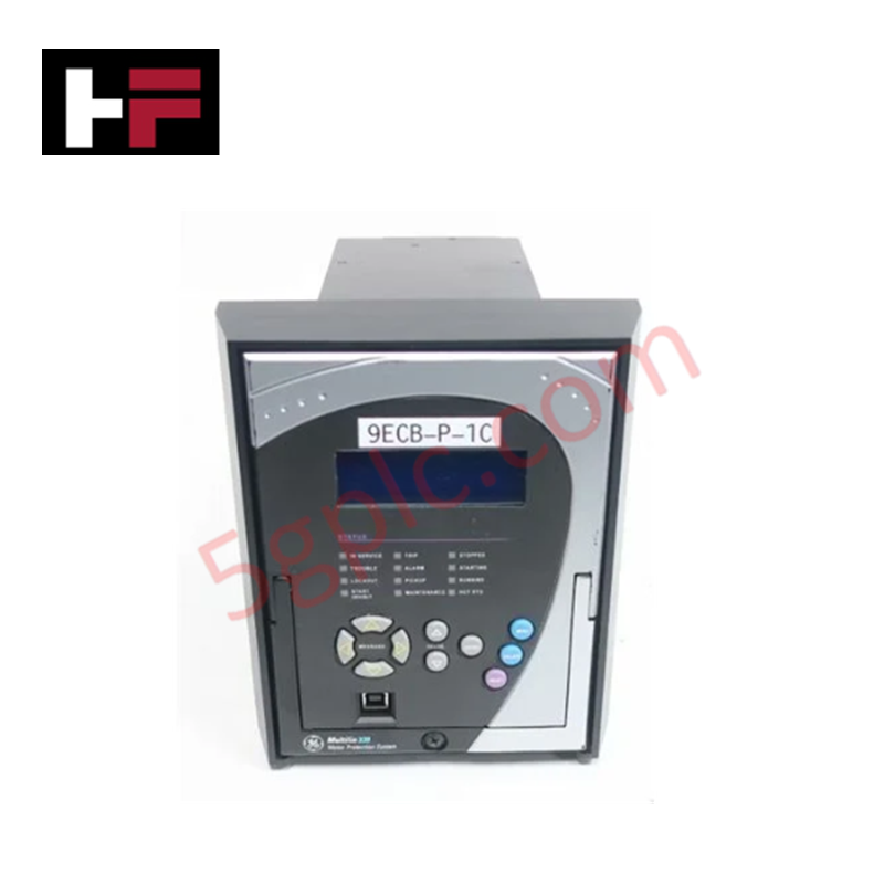
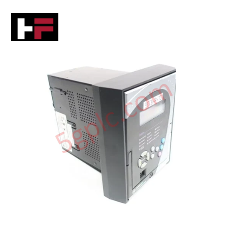
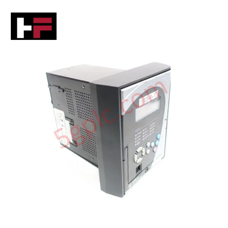
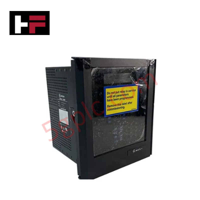
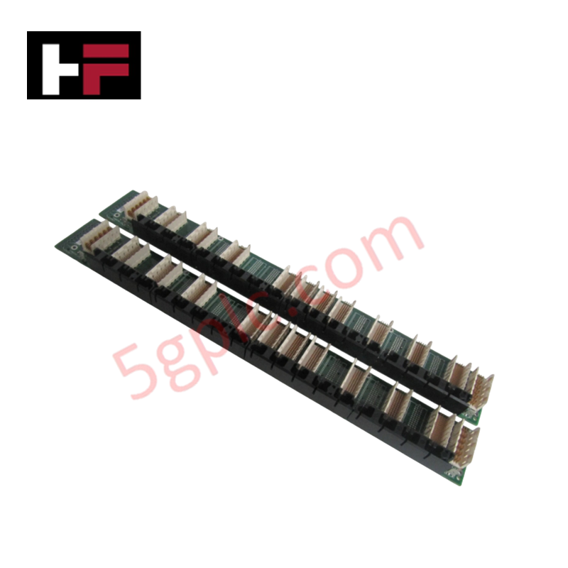
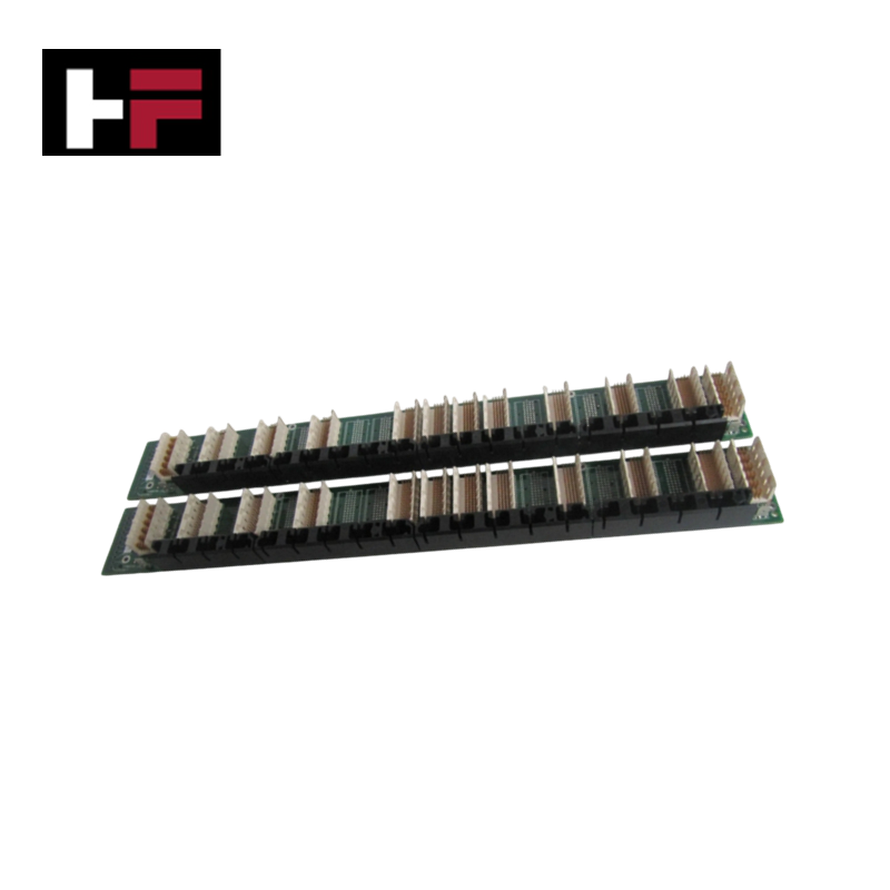
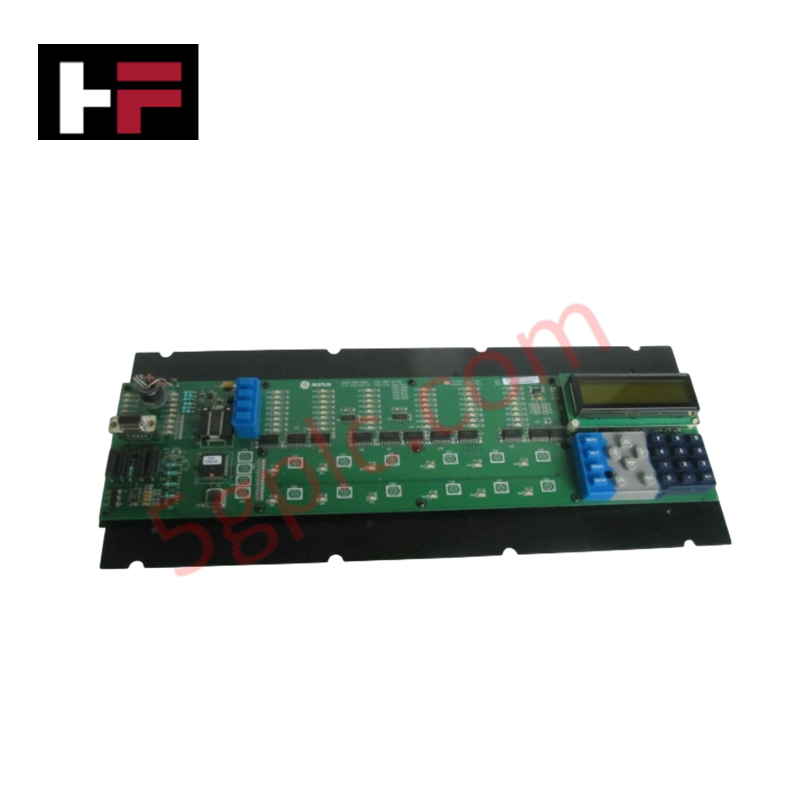
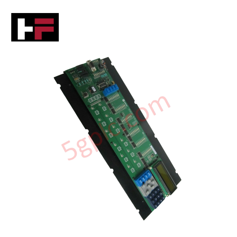
The GE UR8BV, also cataloged as the UR8BV CT/VT Module, operates as a dedicated hardware component for 3-phase analog current and voltage signal conditioning within GE Multilin Universal Relay (UR) platforms.
Hardware Specifications
| Parameter | Specification |
|---|---|
| Model | UR8BV |
| Brand | GE (GE Multilin) |
| Origin | USA |
| Power Consumption | Powered via UR main chassis backplane |
| Input Signals | 3-phase AC current and voltage from field CTs and VTs |
| Accuracy Class | 0.2s or 0.5s (configuration dependent) |
| System Series | Multilin UR Series |
| Product Type | Analog Input Modules |
| System Diagnostics | Onboard circuit health monitoring and internal fault diagnostics |
Backplane Communication Velocity & Deterministic Processing
The UR8BV conditions and digitizes secondary current and voltage signals from external CTs and VTs, feeding accurate analog samples directly to the host protection processor. Transmission of digitized waveform parameters occurs over internal high-speed buses designed to optimize backplane bus communication velocity and cycle synchronization.
Integration within Profinet / EtherNet/IP deterministic networks enables real-time distribution of power metrics and waveform events across connected control networks. The card architecture supports flexible I/O density scaling inside the sub-rack frame while maintaining strict firmware flash compatibility across standard GE Multilin UR protection software revisions.
Frequently Asked Questions
Q: What primary analog inputs does the UR8BV module accept from field instrumentation?
A: The module accepts secondary 3-phase AC current and 3-phase AC voltage inputs from external current transformers (CTs) and voltage transformers (VTs).
Q: What measurement accuracy classes are supported by the UR8BV sampling circuitry?
A: Depending on the exact hardware build and firmware configuration, the module operates at an accuracy class of 0.2s or 0.5s.
Q: Is live insertion or hot-swapping supported for the UR8BV card during active relay operation?
A: No. Auxiliary control power and all primary CT/VT signal circuits must be fully isolated before inserting or removing the module to prevent backplane damage and hazardous open-CT high voltages.
Field Installation Guidelines
- Power & Field Isolation: De-energize all primary rack power feeds and short-circuit all connected CT secondary loops before performing physical installation or removal.
- Grounding Safety: Connect a grounded ESD wrist strap to an unpainted metal chassis earth point prior to handling the module assembly.
- Card Alignment: Slide the module into the designated UR rear chassis slot using the plastic internal guide channels to ensure correct mechanical alignment.
- Connector Seating: Firmly push the card home to engage the multi-pin backplane interface, then hand-tighten the top and bottom panel retaining screws.
- Field Wiring Integrity: Connect CT and VT wiring to the designated rear terminal blocks. Ensure all signal cable shields are grounded at a single chassis earth bar to prevent EMI interference on analog lines.
Additional Information
- 100% Genuine Parts: All products are original and authentic, ensuring reliable industrial performance.
- 30-Day Refund Guarantee: Return any in-stock item within 30 days in original, unopened packaging for a full refund (excluding shipping and fees).
- 12-Month Warranty: Covers defects in materials or workmanship; excludes misuse, normal wear, or unauthorized modifications.
- Worldwide Shipping: We ship via USPS, UPS, FedEx, and DHL. Delivery times vary by country and may be subject to customs or import fees.
- Support & Contact: Technical and warranty assistance is available anytime. Contact us here: Contact.
- Purchase Guidance: Check product specifications and compatibility carefully before ordering to ensure proper application.


Tech & Buying Guide

Will PLCs Become Obsolete? The Future of Control Systems in Industry 4.0
Modern manufacturing is undergoing a rapid technological transformation driven by Industry 4.0 innovations. Technologies like Artificial Intelligence (AI), Machine Learning (ML), and the Industrial Internet of Things (IIoT) are dominating discussions across the factory automation sector. Consequently, many engineers wonder if these advanced digital tools will eventually replace traditional Programmable Logic Controllers (PLCs). However, evaluating the core physics of industrial operations reveals a very different reality for control systems.

Demystifying Open Platform Communication (OPC): The Backbone of Industrial Interoperability
Interoperability remains a cornerstone requirement for modern smart factories and process automation. Open Platform Communication (OPC) bridges the gap between disparate hardware platforms, control systems, and visualization software. By establishing a universal communication standard, OPC allows field controllers, SCADA platforms, and enterprise software from different vendors to exchange real-time data seamlessly.

Understanding Siemens PLC Memory Cards: MMC, SMC, and SD Solutions in Industrial Automation
Memory management plays a pivotal role in maintaining control system reliability across modern manufacturing plants. Industrial control systems rely on specialized memory cards to store project logic, firmware updates, and retentive system data. Siemens uses several memory architectures, including Micro Memory Cards (MMC) and SIMATIC Memory Cards (SMC). Engineers must understand these hardware variations to ensure zero data loss and minimize downtime during maintenance routines.