










Product Details
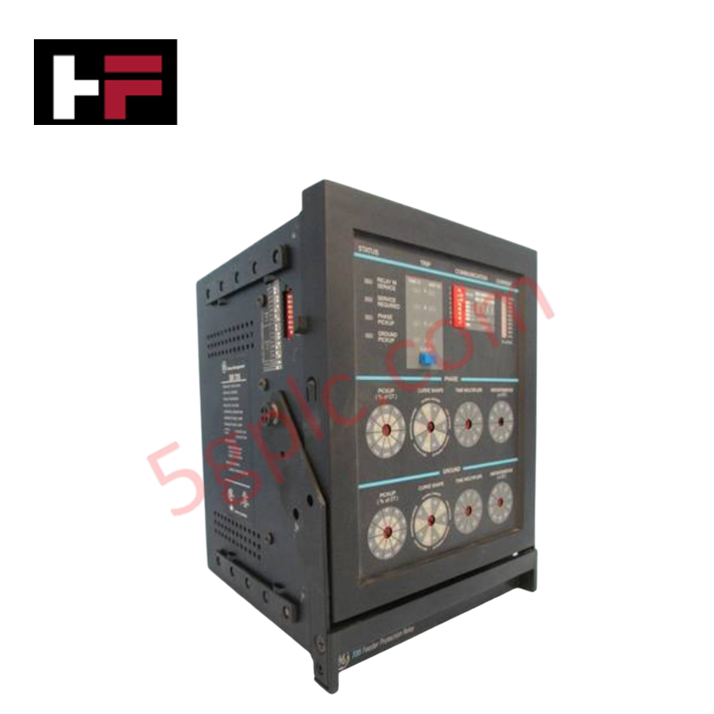
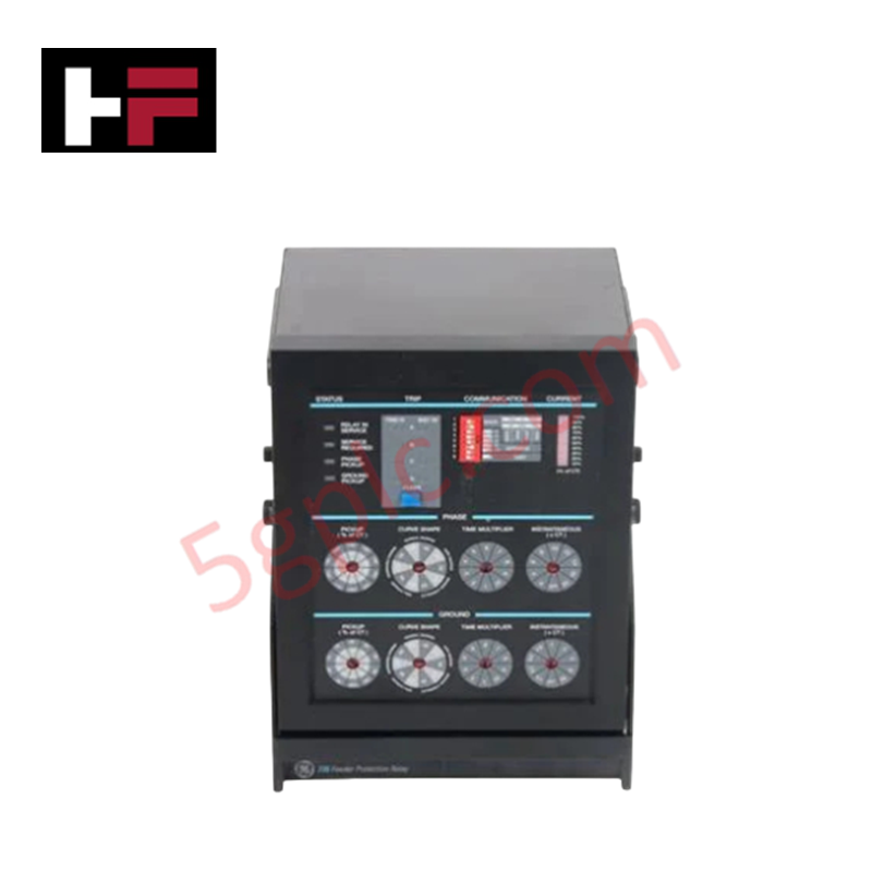
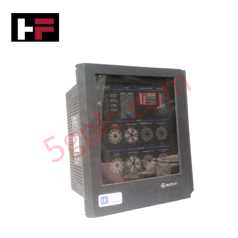
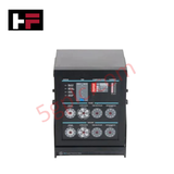
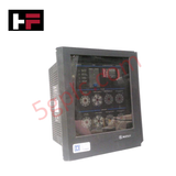
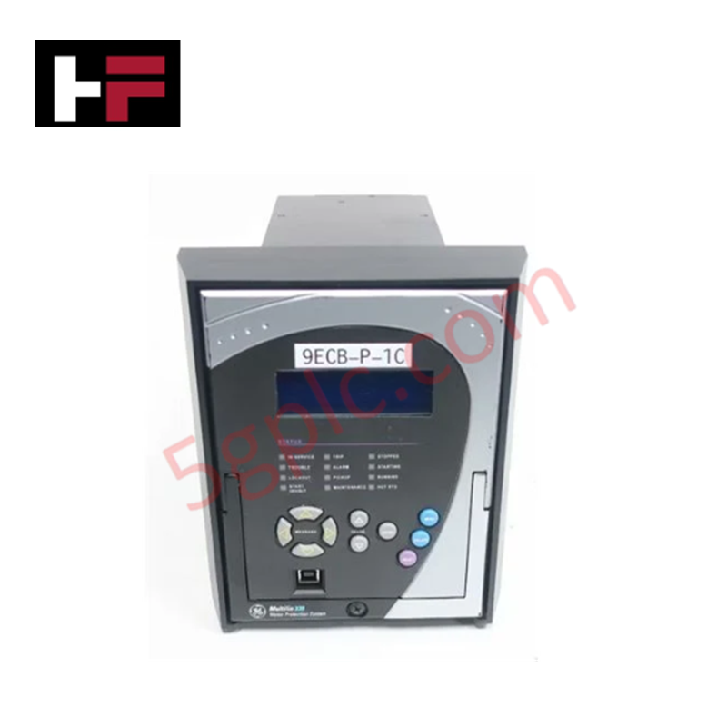
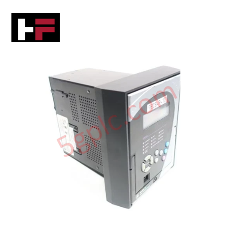
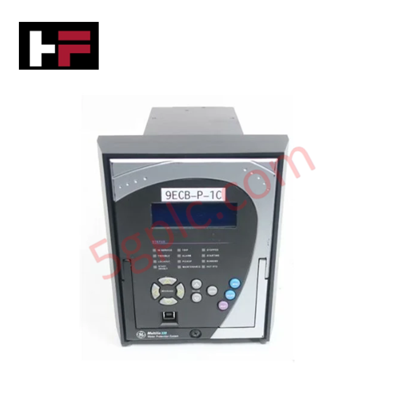
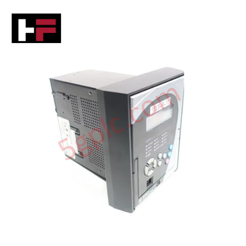
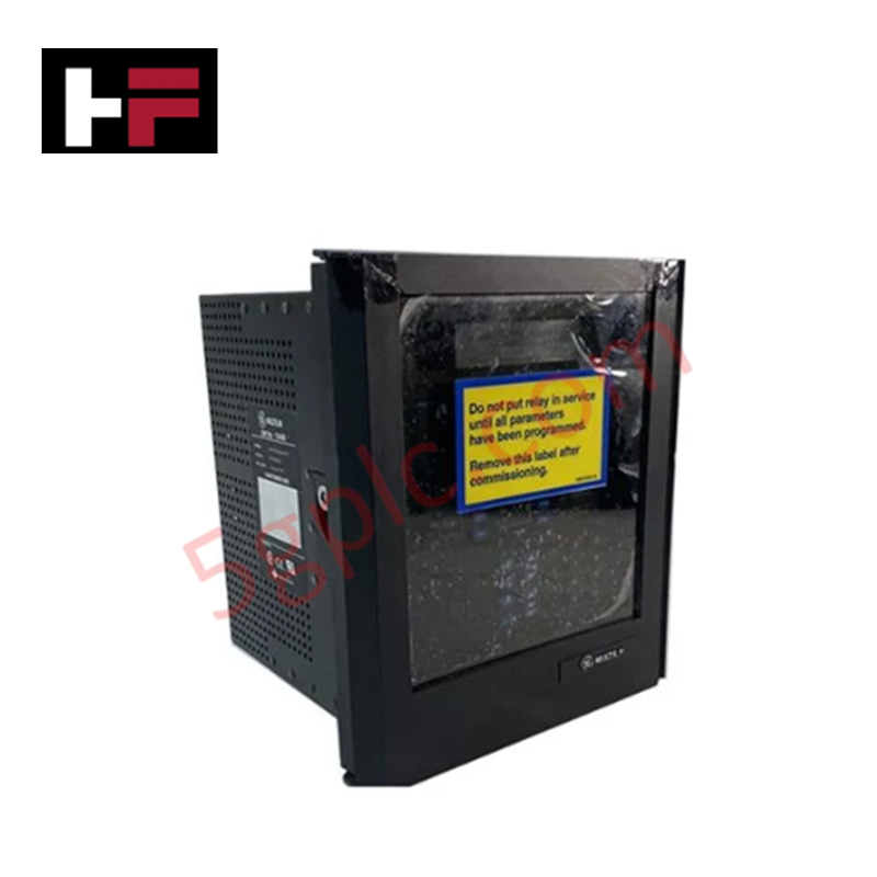
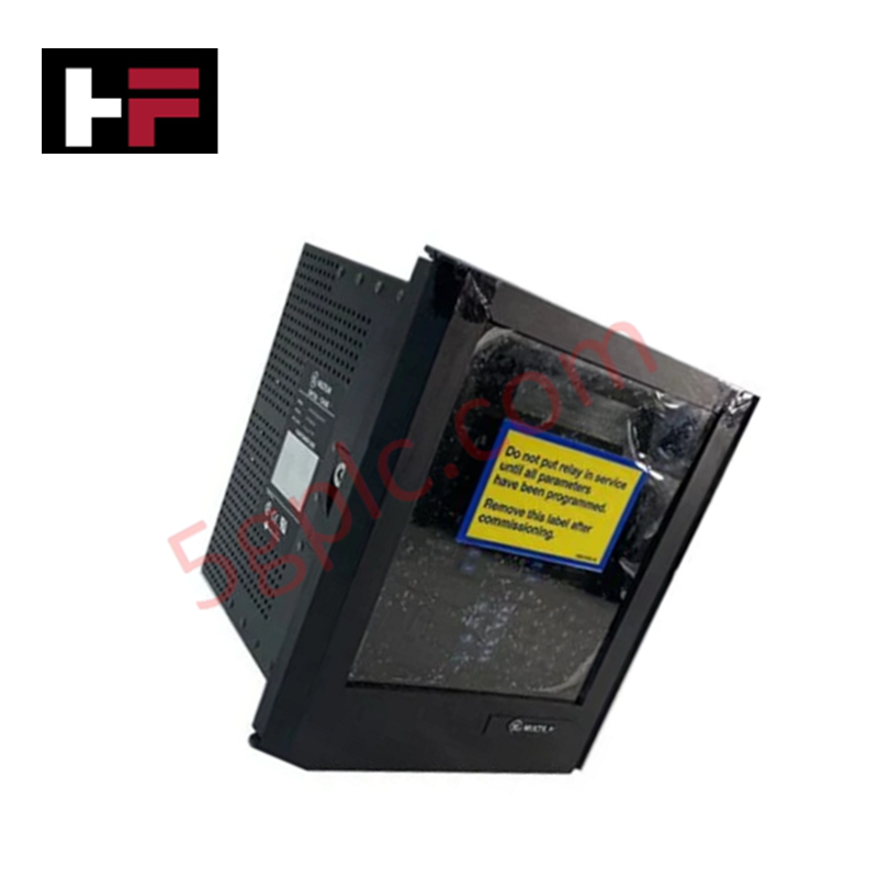
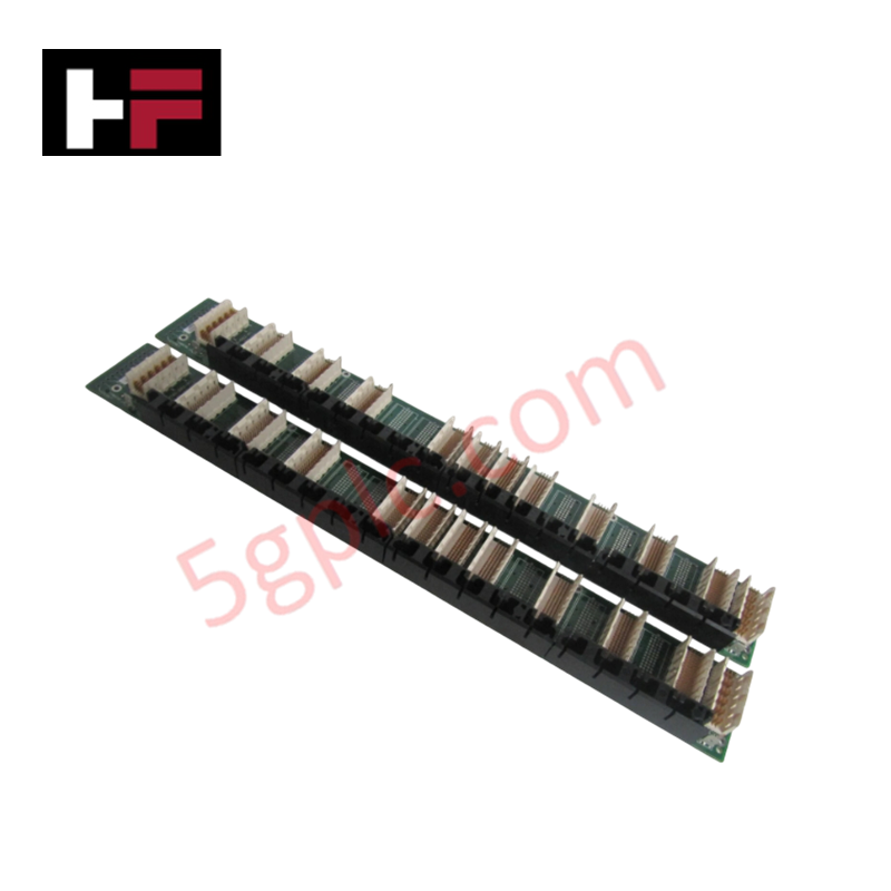
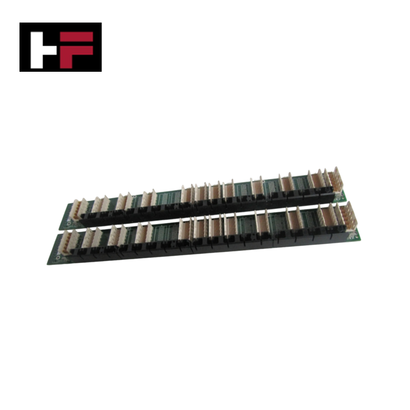
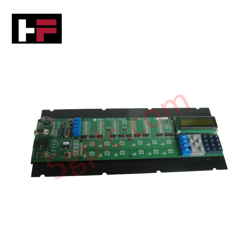
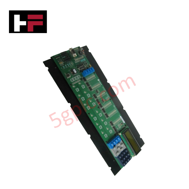
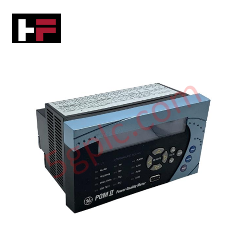
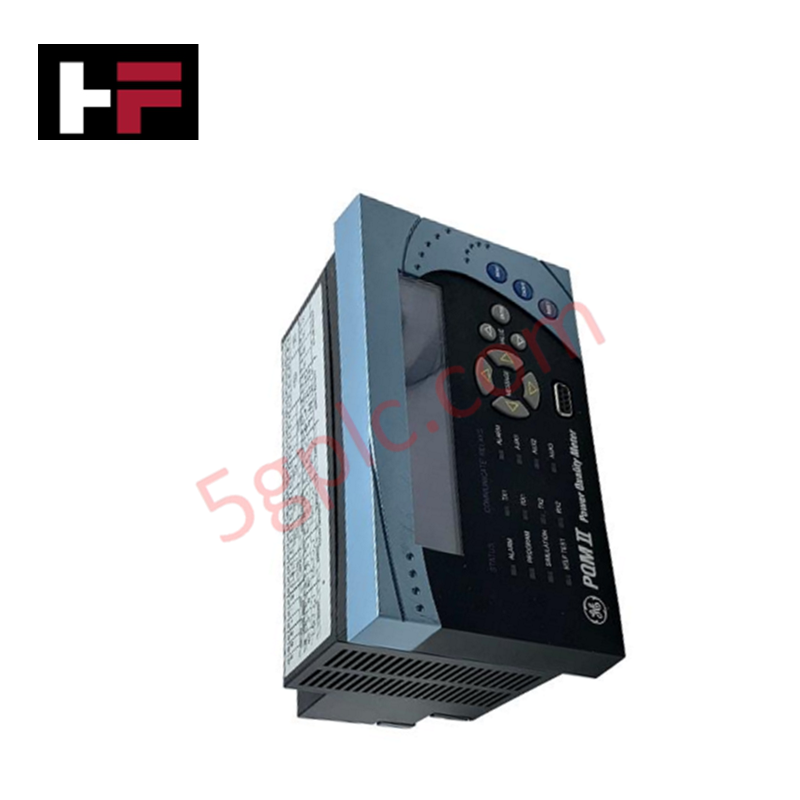
The GE SR-735-5-5-HI-485, also cataloged as the SR735 Feeder Protection Relay, operates as a dedicated hardware component for overcurrent protection and fault detection within utility and industrial distribution network infrastructure.
Hardware Specifications
| Parameter | Specification |
|---|---|
| Model | SR-735-5-5-HI-485 |
| Brand | GE Multilin |
| Origin | Canada / United States |
| Weight | 5.35 kg (11.79 lbs) |
| Dimensions | Standard SR735 Panel Mount Profile |
| Operating Temp | -20 - 60 deg C |
| Power Consumption | Control Power: 90 - 300 VDC, 70 - 265 VAC @ 50/60 Hz |
| Protection Elements | 50/51 (Phase Overcurrent), 50G/51G (Ground Overcurrent) |
| Phase CT Secondary | 5 A |
| Ground CT Secondary | 5 A |
| Local Interface | RS485 2-wire serial connection |
Firmware Flash Compatibility and Processing Architecture
The relay evaluates secondary current transformers scaled for 5 A nominal inputs, driving dedicated protective math channels directly inside the hardware execution loop. Phase and ground overcurrent states execute based on ANSI 50/51 and 50G/51G curve computations. Synchronous logic integration with local substation SCADA architectures requires matching firmware flash compatibility layers across the RS485 2-wire serial link to prevent communication buffer timeout errors during heavy transient trip events.
Frequently Asked Questions
Q: Can the SR-735-5-5-HI-485 relay chassis be withdrawn or hot-swapped while the secondary CT circuits are live?
A: No. The current transformer secondary circuits must be externally shorted via a test switch block before any chassis removal. Extracting a live relay card without shorting the CT circuit will induce destructive open-circuit high voltage across the terminal block.
Q: How is the RS485 network topology affected during firmware flash compatibility adjustments?
A: Firmware differences between individual nodes can reset device address and baud rate registers to factory defaults. Substation automation loops must verify matching register mapping configurations post-flashing to maintain deterministic poll schedules.
Field Installation Guidelines
- Current Transformer Termination: Attach all 5 A phase and ground CT secondary wires firmly to the specified high-current screw terminal strip, ensuring minimum contact resistance.
- RS485 Serial Link Isolation: Route the RS485 2-wire serial network cabling using shielded twisted-pair (STP) conductors, keeping physical separation from heavy power bus lines.
- Control Voltage Grounding: Terminate the shield layer of the communication cable at one single point in the grid, and ensure the relay chassis ground lug links directly to the local sub-station earth ground bar.
Additional Information
- 100% Genuine Parts: All products are original and authentic, ensuring reliable industrial performance.
- 30-Day Refund Guarantee: Return any in-stock item within 30 days in original, unopened packaging for a full refund (excluding shipping and fees).
- 12-Month Warranty: Covers defects in materials or workmanship; excludes misuse, normal wear, or unauthorized modifications.
- Worldwide Shipping: We ship via USPS, UPS, FedEx, and DHL. Delivery times vary by country and may be subject to customs or import fees.
- Support & Contact: Technical and warranty assistance is available anytime. Contact us here: Contact.
- Purchase Guidance: Check product specifications and compatibility carefully before ordering to ensure proper application.
Tech & Buying Guide

Transforming Shop Floor Data into Actionable Insights: A Deep Dive into MES
Manufacturing Execution Systems serve as the digital backbone of modern factory floors. Positioned at Level 3 of the ISA-95 automation pyramid, MES links enterprise resource planning with real-time shop floor control systems. Today, industrial operators rely on MES software to bridge operational strategy with physical production execution.

Managed Switch vs. Unmanaged Switch: Industrial Ethernet Architecture

Hot Standby vs. Cold Standby Redundancy in Industrial Automation
System availability determines process safety and productivity in industrial automation. Control engineers deploy redundancy to eliminate single points of failure. This technical guide evaluates Hot Standby vs. Cold Standby architectures, comparing failover speeds, memory sync, cost trade-offs, and field selection criteria.