










Product Details
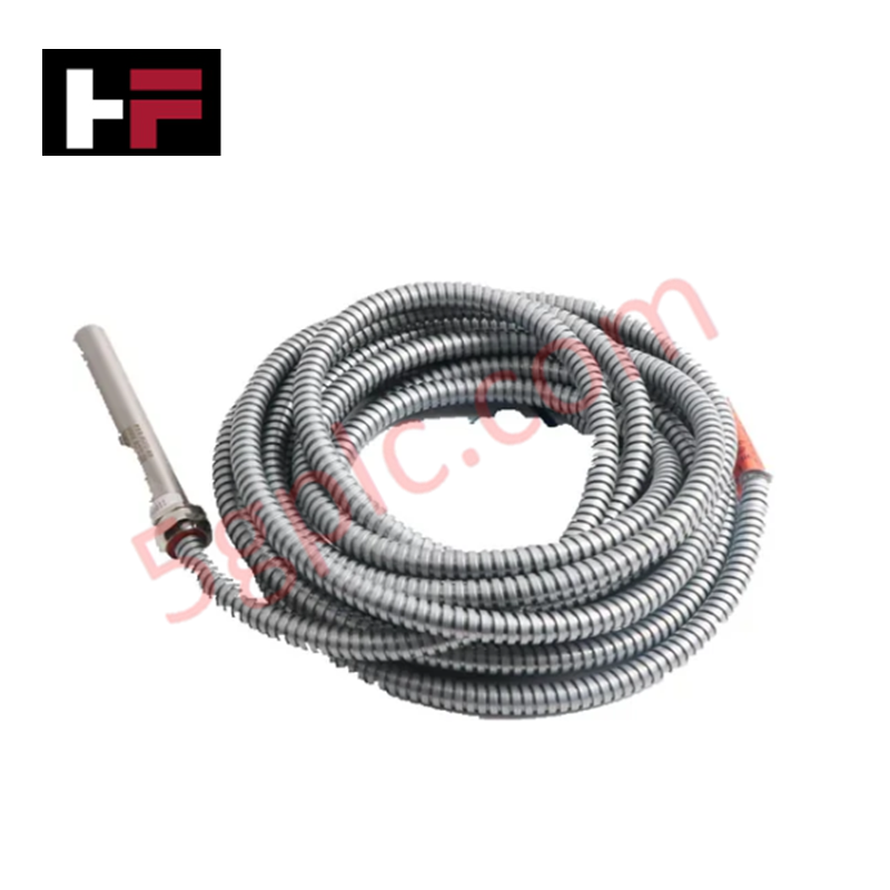
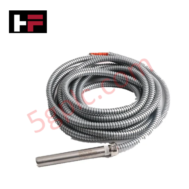
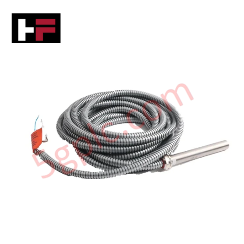
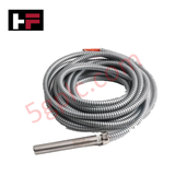
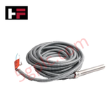
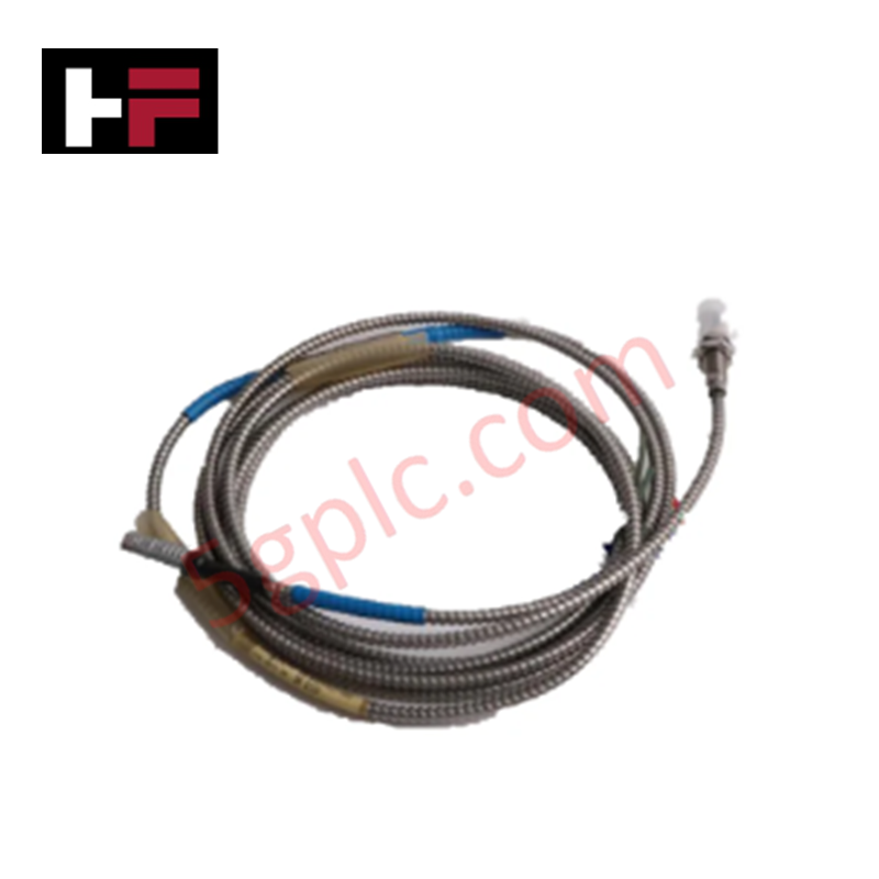
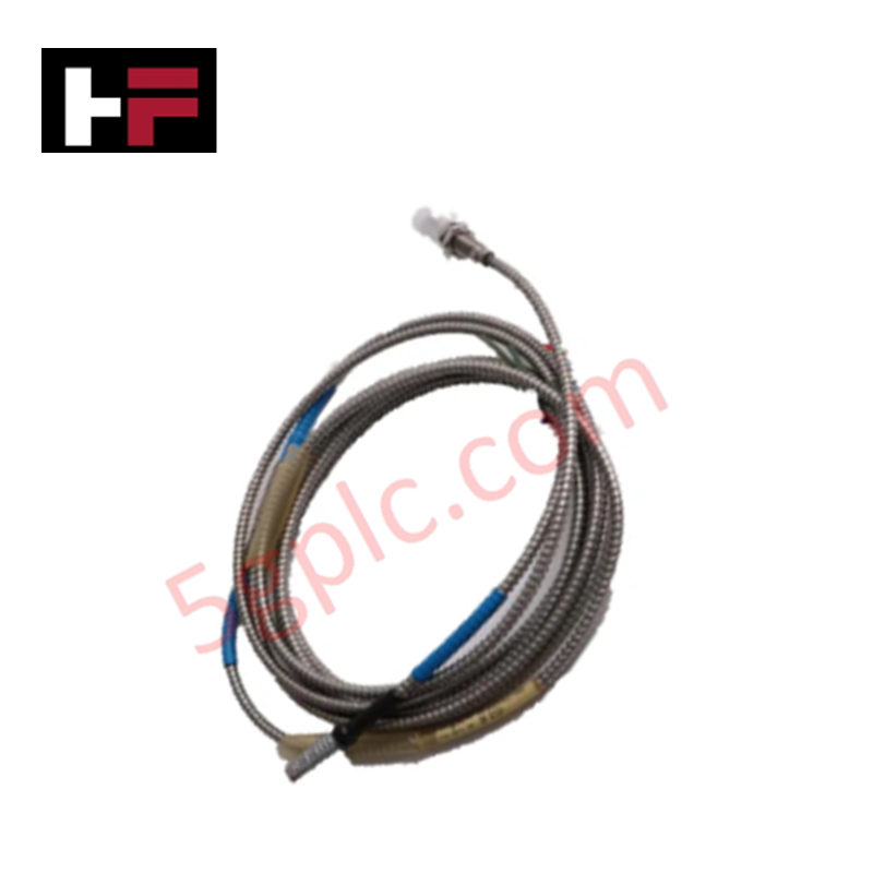
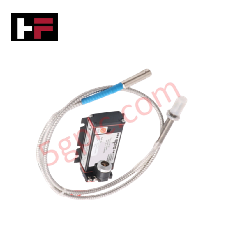
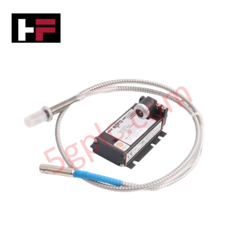
Configured for rotational velocity acquisition in industrial machinery, the Epro PR9376/20 (PR9376/20) Hall-Effect Speed Sensor provides direct electrical execution of non-contact pulse generation from rotating ferromagnetic targets.
Hardware Specifications
| Parameter | Specification |
|---|---|
| Model | PR9376/20 |
| Brand | Epro |
| Weight | 210 g |
| Dimensions | 14 mm diameter, 160 mm length |
| Operating Temp | -25 deg C to +100 deg C |
| Power Consumption | Approx. 25 mA (10-30 VDC) |
| Output | Square wave pulse (High >10 V / Low <1 V) |
| Frequency Capability | Up to 12 kHz |
| Air Gap | 1.0 mm (Module 1) to 1.5 mm (Module >2) |
Mechanical Monitoring and TSI Characteristics
The PR9376/20 operates using Hall-effect magnetic detection to monitor shaft speed by tracking the passage of gear teeth or keyways. To ensure signal fidelity, maintain the specified air gap strictly; deviation from the 1.0 mm or 1.5 mm tolerance will degrade pulse amplitude and timing accuracy. In multi-sensor TSI arrays, ensure proper cable routing to prevent cross-talk between high-speed signal channels, as external electromagnetic interference can distort the square wave transition. The sensor’s output is proportional to target passage, requiring a clean ferromagnetic target surface—typically non-stainless steel—to avoid pulse dropout or erratic switching.
Frequently Asked Questions
Q: Is the 12 kHz frequency capability sufficient for all turbine applications?
A: The 12 kHz limit covers most standard industrial applications. For high-speed rotors with high-tooth-count gears, ensure the calculated pulse frequency $f = \frac{N \times RPM}{60}$ does not exceed the sensor's bandwidth to prevent missing pulses or output saturation.
Q: How should the sensor be oriented relative to the gear teeth?
A: The sensor must be mounted perpendicular to the target surface. The active tip must face the ferromagnetic material directly to achieve the magnetic flux variation required to trigger the Hall-effect switch logic.
Field Installation Guidelines
- Ensure the mounting bracket is rigid to avoid vibration-induced changes to the air gap, which can cause intermittent signal loss.
- Terminate the PTFE-insulated cable at the monitoring system input; ensure the shield is connected at the control cabinet side to mitigate interference.
- Check the target material properties; ensure it is a soft magnetic steel to maintain optimal flux density for the Hall-effect element.
- Verify the power supply voltage is within the 10-30 VDC range and that the load resistance is configured for the typical 100 kOhm operation.
- Perform a commissioning test by manually rotating the shaft at low speed to confirm square wave pulse generation before applying full operational velocity.
Additional Information
- 100% Genuine Parts: All products are original and authentic, ensuring reliable industrial performance.
- 30-Day Refund Guarantee: Return any in-stock item within 30 days in original, unopened packaging for a full refund (excluding shipping and fees).
- 12-Month Warranty: Covers defects in materials or workmanship; excludes misuse, normal wear, or unauthorized modifications.
- Worldwide Shipping: We ship via USPS, UPS, FedEx, and DHL. Delivery times vary by country and may be subject to customs or import fees.
- Support & Contact: Technical and warranty assistance is available anytime. Contact us here: Contact.
- Purchase Guidance: Check product specifications and compatibility carefully before ordering to ensure proper application.




Tech & Buying Guide

Human-Machine Interface Design: Essential Guide to HMI Selection, Visualization, and Control System Integration
Human-Machine Interfaces (HMIs) serve as the primary operational window into complex industrial automation systems. Modern HMIs convert raw machine data into clear graphical displays, enabling operators to oversee entire manufacturing processes in real time. Instead of relying on physical control panels full of hardwired switches, engineers program interactive screens using intuitive graphics, dynamic color coding, and responsive touch interfaces. Over my 15 years in control systems engineering, I have observed HMIs transform from basic display screens into sophisticated command centers that drive operational efficiency across DCS and PLC environments.

Understanding Safety Relays in Industrial Automation: Architecture, Operation, and Functional Safety
Standard electromechanical relays provide basic electrical isolation between low-voltage control circuits and high-power output loads. A traditional switching relay features a magnetic coil driving mechanical Common (COM), Normally-Open (NO), and Normally-Closed (NC) contacts. However, standard relays pose severe functional risks when deployed in critical safety interlock circuits. High current inrush or mechanical wear can weld contacts together permanently. If contact welding occurs in an emergency stop circuit, pressing the button fails to halt hazardous machinery movements. Consequently, global functional safety standards prohibit standard relays for critical machine guarding functions.

Mastering Wire Identification in Industrial Automation: The Power of Ferrules and Cross-Ferruling
Proper wire labeling forms the cornerstone of reliable control system installation and long-term maintenance. In complex industrial automation environments, technicians terminate thousands of conductor ends inside control panels, marshalling racks, and field junction boxes. Ferrules serve as individual tube-shaped sleeve markers slipped onto conductors before final termination. While technicians historically relied on pre-printed individual letter rings, modern control panel builders utilize automated ferrule printing machines. These thermal-transfer printers generate durable, single-sleeve heat-shrink tags directly matching approved wiring schematics, significantly accelerating cabinet assembly workflows.