










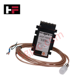
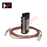
Product Details
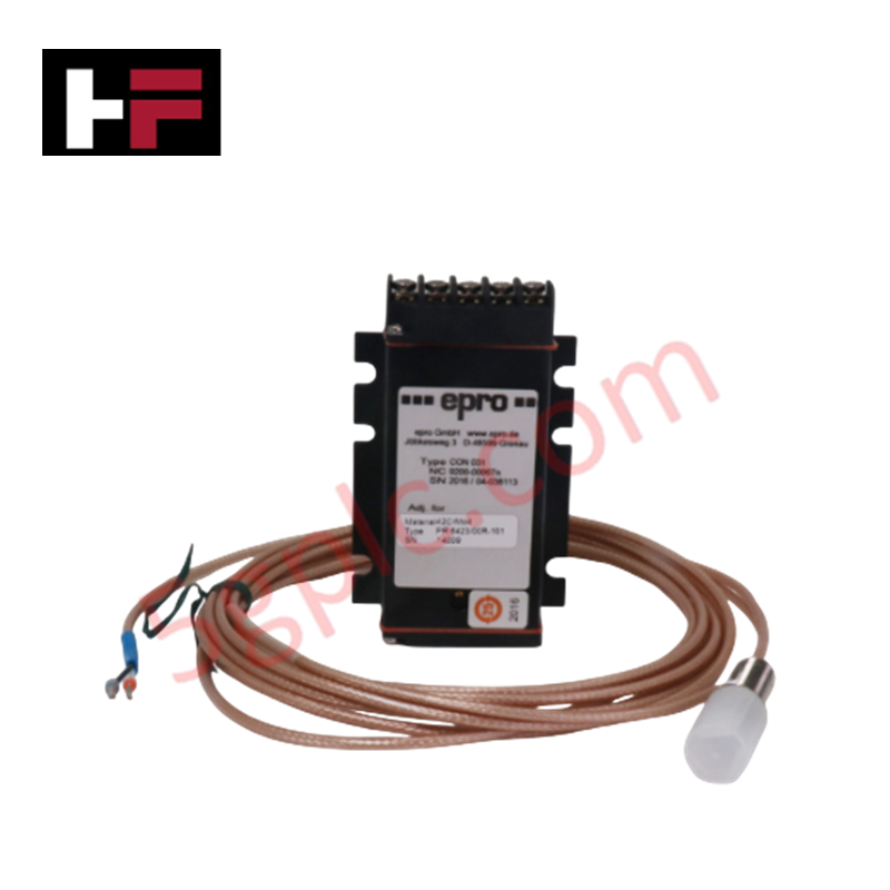
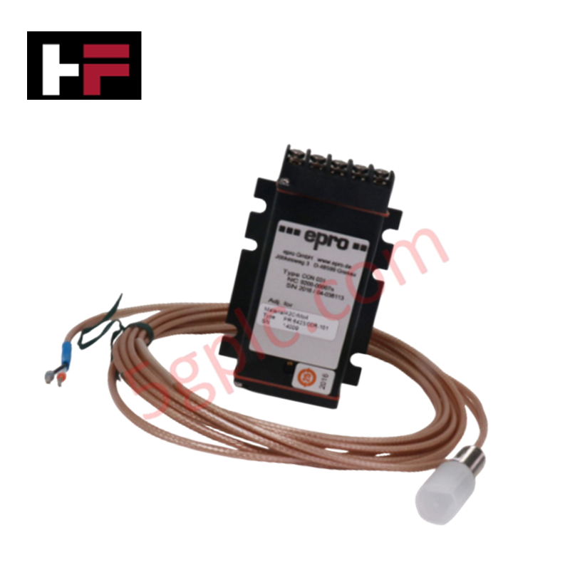
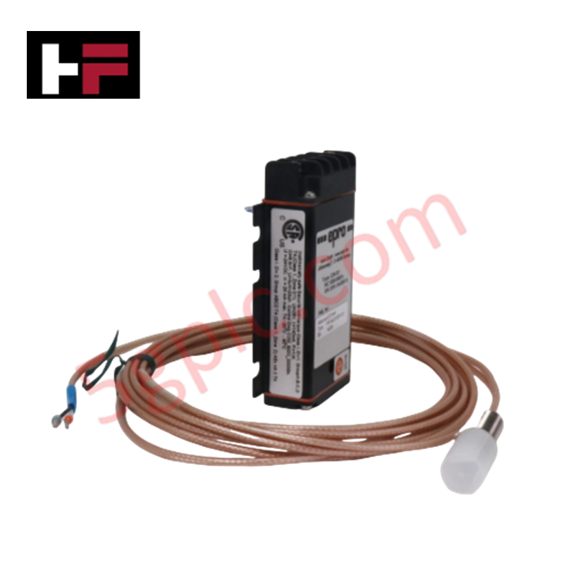
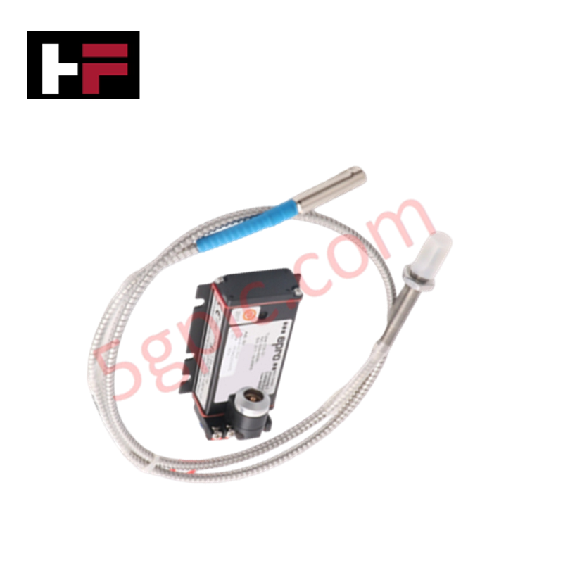
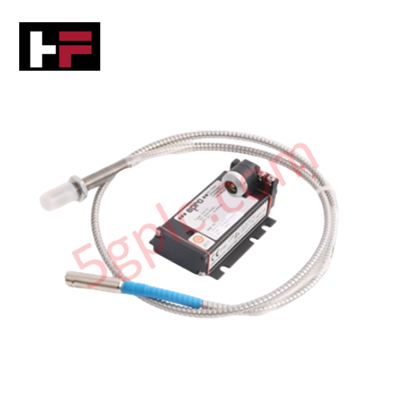
The Emerson PR6423/00N-030, also cataloged as the PR6423/00N-030 Eddy Current Displacement Transducers, operates as a dedicated hardware component for non-contact dynamic shaft displacement and position measurement within turbomachinery protection systems. The transducer conditions electromagnetic flux variations generated by target proximity to measure radial and axial shaft dynamic displacement, position, eccentricity, and speed without physical contact.
Hardware Specifications
| Parameter | Specification |
|---|---|
| Model | PR6423/00N-030 |
| Brand | Emerson |
| Origin | Germany |
| Operating Temp | Sensor: -35 to +180 deg C (-31 to 356 deg F); Short-term (up to 5 hours): Up to +200 deg C (392 deg F) |
| Power Consumption | Powered via external driver/signal converter supply rail |
| Measurement Principle | Non-contact eddy current inductive sensing |
| Measurement Capabilities | Radial and axial shaft dynamic displacement, position, eccentricity, speed |
| Thermal Resistance | Continuous operation up to +180 deg C, excursion up to +200 deg C |
| Physical Design | Ruggedized vibration-resistant compact probe construction |
| Product Type | Eddy Current Displacement Transducers |
4-20 mA HART Loop Protocol and Channel Isolation
The signal conversion hardware coupled to the PR6423/00N-030 utilizes channel-to-channel isolation architecture to decouple primary inductive sensing loops from plant auxiliary power rails and ground noise. When interfaced into DCS platforms operating 4-20 mA HART loop protocol transmitters or FOUNDATION Fieldbus signal interface gateways, the transducer loop maintains high frequency linearity. Thermal compensation circuitry provides cold junction compensation tracking to stabilize measurement accuracy during environmental temperature shifts across the -35 to +180 deg C operational limits.
Frequently Asked Questions
Q: What are the extended thermal exposure limits for the PR6423/00N-030 sensor head?
A: The sensor supports continuous operation from -35 to +180 deg C (-31 to 356 deg F) and can tolerate short-term thermal excursions up to +200 deg C (392 deg F) for periods up to 5 hours.
Q: How does non-contact eddy current sensing function in shaft displacement monitoring?
A: The probe generates a high-frequency electromagnetic field at the tip; physical target movements alter eddy current losses, producing a proportional voltage change evaluated by downstream signal converters.
Q: Does the sensor require external power directly at the probe head?
A: No, the passive inductive transducer head is driven and powered directly via coaxial connection from an external signal converter module.
Field Installation Guidelines
- Inspect the target shaft region to verify surface finish is free from scratch defects, mechanical runout, and residual magnetism.
- Mount the PR6423 probe head into its machine casing bracket perpendicular to the rotating shaft centerline.
- Adjust the static air gap using non-magnetic shims or by measuring static output bias voltage prior to securing the housing.
- Torque the outer mounting locknut against the bracket to prevent physical displacement caused by operational machine vibration.
- Route the integral transducer cable through grounded rigid or flexible metallic conduit away from high-voltage motor wiring.
- Connect the outer cable shield to the single-point instrument ground bus inside the field termination enclosure.
Additional Information
- 100% Genuine Parts: All products are original and authentic, ensuring reliable industrial performance.
- 30-Day Refund Guarantee: Return any in-stock item within 30 days in original, unopened packaging for a full refund (excluding shipping and fees).
- 12-Month Warranty: Covers defects in materials or workmanship; excludes misuse, normal wear, or unauthorized modifications.
- Worldwide Shipping: We ship via USPS, UPS, FedEx, and DHL. Delivery times vary by country and may be subject to customs or import fees.
- Support & Contact: Technical and warranty assistance is available anytime. Contact us here: Contact.
- Purchase Guidance: Check product specifications and compatibility carefully before ordering to ensure proper application.




Tech & Buying Guide

Demystifying the DDE Protocol in Legacy Industrial Automation Systems
Modern control systems rely heavily on seamless interprocess communication to exchange operational data between software programs. Microsoft first introduced the Dynamic Data Exchange (DDE) protocol in 1987 to enable real-time data sharing. In factory automation, DDE served as an early bridge between control software and Windows desktop applications. Therefore, understanding DDE mechanics provides crucial insights into how legacy industrial networks established software-level connectivity.

Demystifying CPU Communication Ports in Siemens PLC Architectures
Industrial automation relies heavily on robust data exchange between devices. Without seamless connectivity, field instruments, network switches, human-machine interfaces, and programmable logic controllers cannot coordinate effectively. Therefore, understanding the various CPU communication ports available in Siemens hardware ensures efficient factory automation design and seamless system integration.

Mastering the Siemens PLC Scan Cycle: How the CPU Executes Automation Programs
Industrial automation relies heavily on programmable logic controllers (PLCs) to manage complex manufacturing processes. Many engineers dive straight into programming without mastering the underlying architecture. However, understanding how a PLC CPU executes a program ensures reliable system design. Therefore, mastering the scan cycle optimizes both performance and troubleshooting in modern control systems.