


Product Details
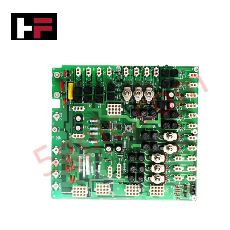
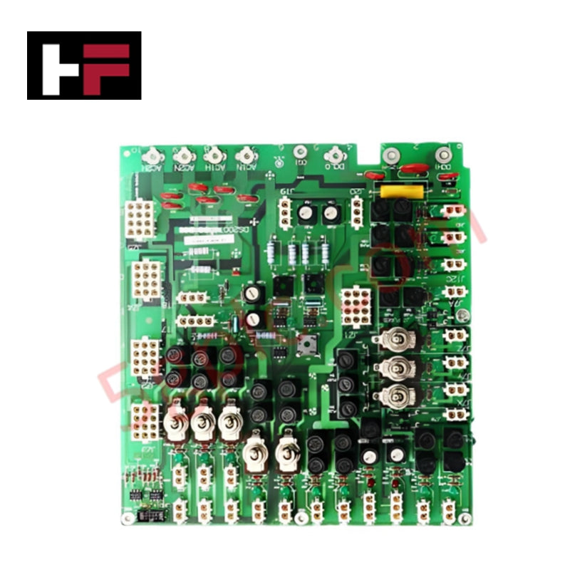
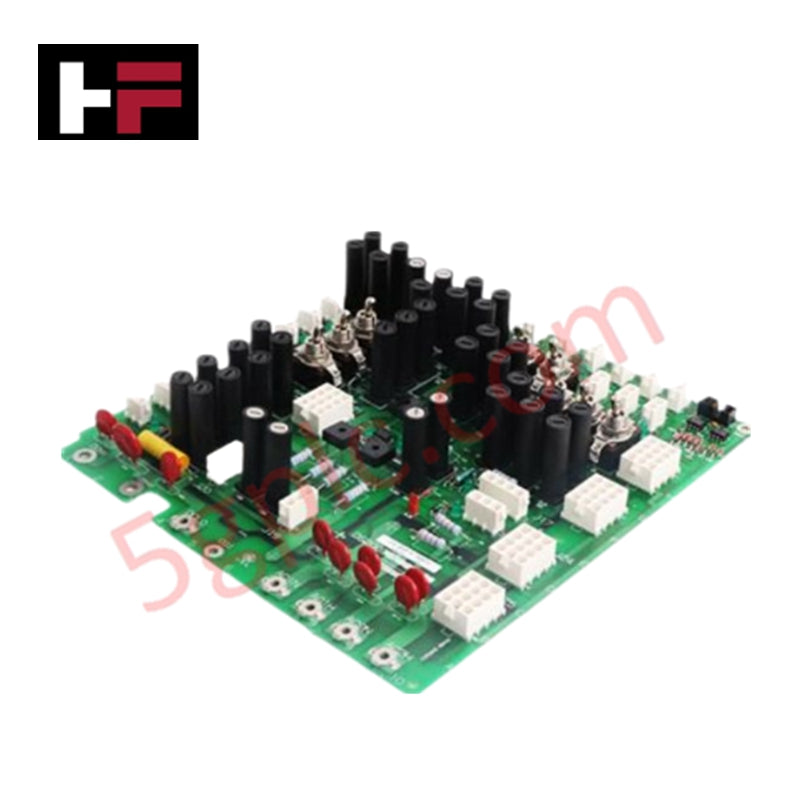
The GE DS200TCPDG1B, also cataloged as the DS200TCPD Power Distribution Module, operates as a dedicated hardware component for power regulation and circuit protection within Mark V turbine control system platforms.
Hardware Specifications
| Parameter | Specification |
|---|---|
| Model | DS200TCPDG1B |
| Brand | GE |
| Origin | USA |
| Core Performance | 8 toggle switches, 36 fuses, 36 OK LEDs, 4 signal terminals |
Industrial Control & Drive Integration
The DS200TCPDG1B supports standard Mark V architecture through fixed-logic power distribution and fault monitoring. Backplane bus communication velocity and I/O density scaling are inherently limited by the module's hard-wired design, which precludes software-based configuration or firmware flash compatibility. Signal integrity is maintained via the manual BJS jumper, which facilitates ground reference isolation for external reference systems. Deterministic fault detection is limited to the physical fuse state, indicated by the integrated 36 OK LEDs, providing real-time local status visibility without reliance on digital network protocols.
Frequently Asked Questions
Q: Is software-based configuration available for this module?
A: No. The DS200TCPDG1B operates exclusively through hard-wired logic. Configuration is restricted to physical switch positioning and the adjustment of the BJS ground reference jumper.
Q: Can the board be configured for different power input ranges?
A: Power conversion is managed by the external DACA PCB. The DS200TCPDG1B module is designed to receive processed power and distribute it across its 36 fused circuits; it does not perform primary power input regulation itself.
Q: What is the purpose of the two red LEDs on the board?
A: The red LEDs serve as fault indicators. If illuminated, they denote a general board-level malfunction, indicating that the module's internal circuitry requires manual inspection and diagnostic verification.
Field Installation Guidelines
- Fuse Replacement: In the event of a blown fuse (indicated by an extinguished OK LED), isolate the board from power before extraction. Ensure replacement fuses meet the original amperage ratings to prevent overcurrent damage to the circuits.
- Jumper Settings: Utilize the BJS jumper to select for ground reference isolation. If the system requires an external ground reference, ensure the jumper is correctly positioned to bridge the circuit to the external system.
- Wiring Termination: When connecting signal wires to the four terminals, ensure that copper conductors are fully seated before tightening the retention screws. Avoid over-torquing to prevent mechanical failure of the terminal block.
- Static Protection: Always handle the PCB using standard anti-static procedures. The module contains sensitive components that may be damaged by electrostatic discharge during handling or installation.
Additional Information
- 100% Genuine Parts: All products are original and authentic, ensuring reliable industrial performance.
- 30-Day Refund Guarantee: Return any in-stock item within 30 days in original, unopened packaging for a full refund (excluding shipping and fees).
- 12-Month Warranty: Covers defects in materials or workmanship; excludes misuse, normal wear, or unauthorized modifications.
- Worldwide Shipping: We ship via USPS, UPS, FedEx, and DHL. Delivery times vary by country and may be subject to customs or import fees.
- Support & Contact: Technical and warranty assistance is available anytime. Contact us here: Contact.
- Purchase Guidance: Check product specifications and compatibility carefully before ordering to ensure proper application.


Tech & Buying Guide

Redundant Automation Systems: Ensuring Continuous Uptime in Critical Control Infrastructure
System reliability directly determines operational profitability across high stakes process industries. Modern industrial automation platforms must eliminate single points of failure to prevent catastrophic shutdowns. Deploying fault tolerant architecture safeguards complex facilities against unexpected hardware glitches, network disruptions, and maintenance outages.

Understanding Types of Noise in Electronic Circuits and Control Systems
Signal integrity directly determines measurement accuracy and loop stability across industrial automation environments. Electronic noise introduces unwanted stochastic interference into analog loops, sensor feedback lines, and digital fieldbus networks. Understanding how intrinsic electronic noise and external electromagnetic interference manifest allows control engineers to optimize signal conditioning and shield sensitive instrumentation effectively.

Why 24V DC Power Supplies Standardize Modern Industrial Automation
Industrial control cabinets worldwide rely on 24V DC as the universal power standard for field instrumentation, sensors, and controllers. Walk into any manufacturing plant, and you will find PLCs, human-machine interfaces (HMIs), and smart actuators running on extra-low voltage DC. Standardizing on 24V DC enhances operational safety, lowers cabinet footprint, and maintains steady control performance across factory networks.