










Product Details
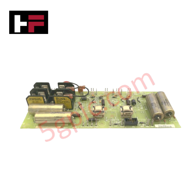
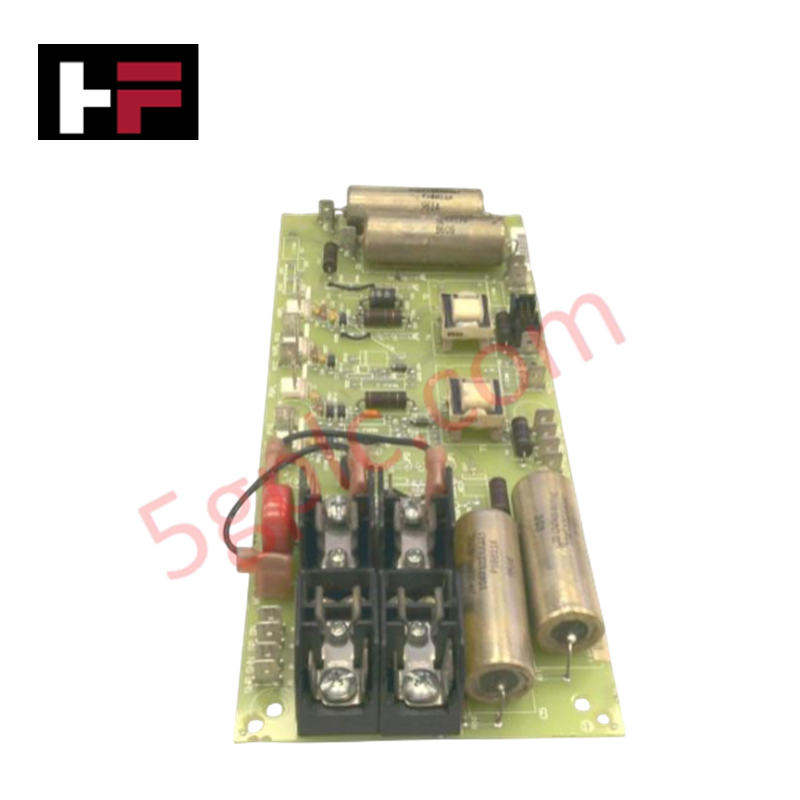
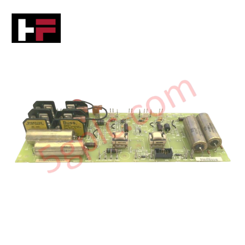
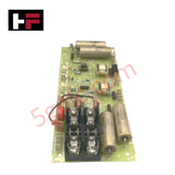
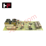
The General Electric DS200FSAAG2A, also cataloged as the DS200FSAAG2A Field Supply Amplifier Board, operates as a dedicated hardware component for thyristor firing signal amplification and drive gate control within Mark V drive control system platforms.
Hardware Specifications
| Parameter | Specification |
|---|---|
| Model | DS200FSAAG2A |
| Brand | General Electric |
| Dimensions | 52 mm x 62 mm |
| Operating Temp | 0 deg C to 50 deg C |
| Power Consumption | Not specified |
| Components | 5 jumpers, 10-pin connector, 2 fuses |
Industrial Control and Drive Systems
The DS200FSAAG2A utilizes integrated circuitry to condition and amplify control signals, regulating the conduction of thyristor bridges through high-speed transistor stages. The board supports firmware flash compatibility via host drive controllers, facilitating the adjustment of firing angles. I/O density scaling is maintained by the board's interface with external field exciter modules, which include metal-oxide varistor (MOV) voltage suppressors and AC/DC line filters. Backplane bus communication velocity governs the timing of gate pulses, ensuring synchronized thyristor switching and transient suppression for field excitation stability.
Frequently Asked Questions (FAQ)
Q: What is the purpose of the 10-pin terminal connector?
A: The 10-pin connector serves as the primary I/O interface for receiving low-level firing signals from the drive control unit and routing them to the internal amplification stages.
Q: How should the jumpers on the board be configured?
A: The board features 5 jumpers for signal path routing and logic level configuration. Refer to the site-specific drive controller schematic to ensure jumpers are set according to the application's excitation requirements.
Field Installation Guidelines
- Static Sensitivity: Use an ESD-rated grounded wrist strap during installation. The board contains integrated circuits and gate-level logic components that are sensitive to electrostatic discharge.
- Fuse Verification: Prior to initial power-up, inspect the two onboard fuses for continuity. Replace any blown fuses with components of identical voltage and current ratings to maintain overcurrent protection for the gate drive circuitry.
- Signal Path Integrity: Verify that the 10-pin connector is fully seated and that the cable assembly is routed away from high-current power cables to prevent electromagnetic interference (EMI) that could corrupt gate firing pulses.
- Test Point Access: The board is equipped with multiple test points for diagnostic verification. Ensure the module is mounted with sufficient clearance to allow for oscilloscope probe access during field commissioning or troubleshooting.
Additional Information
- 100% Genuine Parts: All products are original and authentic, ensuring reliable industrial performance.
- 30-Day Refund Guarantee: Return any in-stock item within 30 days in original, unopened packaging for a full refund (excluding shipping and fees).
- 12-Month Warranty: Covers defects in materials or workmanship; excludes misuse, normal wear, or unauthorized modifications.
- Worldwide Shipping: We ship via USPS, UPS, FedEx, and DHL. Delivery times vary by country and may be subject to customs or import fees.
- Support & Contact: Technical and warranty assistance is available anytime. Contact us here: Contact.
- Purchase Guidance: Check product specifications and compatibility carefully before ordering to ensure proper application.


Tech & Buying Guide

Master Acceptance Testing: Understanding FAT and SAT in Industrial Control Systems
Factory Acceptance Testing (FAT) and Site Acceptance Testing (SAT) serve as critical quality assurance gateways in complex industrial control systems. Both procedures verify that programmable logic controllers (PLCs), distributed control systems (DCS), and associated field devices meet strict functional specifications. However, executing these tests effectively requires clear delineation between off-site staging and final field commissioning.

Industrial Networking Essentials: Demystifying Hubs, Switches, and Routers in Control Systems
Industrial automation relies heavily on robust networking infrastructure to connect programmable logic controllers (PLCs), distributed control systems (DCS), and human-machine interfaces (HMIs). Modern factory automation environments generate vast amounts of real-time operational data across deterministic networks. Understanding the structural differences between hubs, switches, and routers ensures optimal traffic segmentation, minimizes latency, and maintains high network availability.

Safety Relays in Industrial Automation: Fundamentals, Design Standards, and Fail-Safe Architecture
Safety relays form the bedrock of functional safety in modern factory automation, preventing catastrophic equipment failure and protecting plant personnel. While standard electromechanical relays handle basic load switching, they lack the redundant diagnostics required for high-risk industrial environments. Modern industrial automation platforms—including programmable logic controllers (PLCs) and distributed control systems (DCS)—rely on specialized safety relays to monitor field devices and isolate hazards instantly.