


Product Details
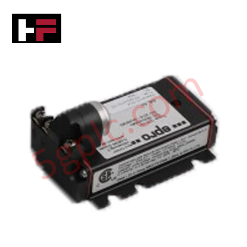
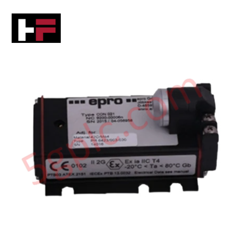
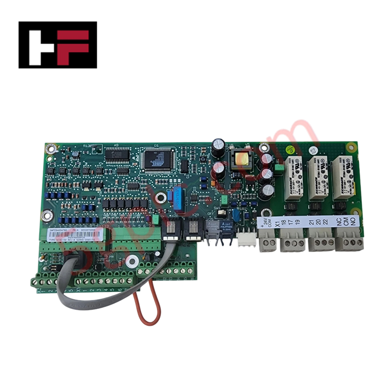
Configured for signal conversion in rotating machinery monitoring networks, the Epro CON020/91 (CON020/91 Signal Conditioner Module Driver) provides direct physical electrical execution for processing transducer inputs into standardized analog signals. The module accepts raw probe inputs and delivers either analog voltage or 4-20 mA current outputs, interfacing directly with TSI monitoring platforms to support continuous data acquisition in machinery protection applications.
Hardware Specifications
| Parameter | Specification |
|---|---|
| Model | CON020/91 |
| Brand | Epro |
| Dimensions | 100 mm x 22 mm x 120 mm |
| Operating Temp | -35 to 85 deg C |
| Input Type | Transducer Signal |
| Output Type | Analog Voltage or 4-20 mA |
Mechanical Monitoring and TSI Characteristics
The CON020/91 module is engineered to manage critical signal parameters for eddy-current probe scaling within machinery protection systems. It supports the precise adjustment of gain and offset required for gap voltage validation against -10 VDC targets, ensuring that the sensor response remains linear across the transducer's measurement range. To preserve data integrity in high-density rack configurations, the module incorporates internal cross-talk suppression and EMI immunity filters, which are required for reliable rotor dynamics analysis under varying load and speed conditions.
Frequently Asked Questions (FAQ)
Q: Can the CON020/91 be hot-swapped while the machinery is operating?
A: Module removal or replacement during active operation depends on the backplane architecture and system configuration. Ensure the I/O channel is inhibited in the monitoring software to prevent a false trip or alarm signal before extracting the module.
Q: Is the 4-20 mA output isolated from the power supply ground?
A: The module is designed for industrial integration where loop isolation is required. Consult the system interconnection diagram to confirm if the output stage requires an external isolator to prevent ground loops between the module and the destination input card.
Field Installation Guidelines
- Mount the module on a standard DIN rail or designated rack chassis, ensuring the mechanical locking clip is fully engaged.
- Terminate signal input cabling using shielded, twisted-pair wire to minimize electromagnetic interference (EMI) ingress.
- Verify that the shield drain wire is bonded to the cabinet earth ground at the rack entry point only to avoid ground loops.
- Set the internal jumpers or configuration switches to match the desired output mode (voltage or current) before applying 24 VDC power.
- Confirm stable signal output at the terminal block using a calibrated multimeter prior to validating the sensor gap voltage at the probe tip.
Additional Information
- 100% Genuine Parts: All products are original and authentic, ensuring reliable industrial performance.
- 30-Day Refund Guarantee: Return any in-stock item within 30 days in original, unopened packaging for a full refund (excluding shipping and fees).
- 12-Month Warranty: Covers defects in materials or workmanship; excludes misuse, normal wear, or unauthorized modifications.
- Worldwide Shipping: We ship via USPS, UPS, FedEx, and DHL. Delivery times vary by country and may be subject to customs or import fees.
- Support & Contact: Technical and warranty assistance is available anytime. Contact us here: Contact.
- Purchase Guidance: Check product specifications and compatibility carefully before ordering to ensure proper application.

Tech & Buying Guide

Navigating Industrial Automation Failures: Types, Causes, and Mitigation Strategies
Modern manufacturing relies heavily on automated control systems to maximize throughput and maintain product quality. However, unplanned downtime in industrial automation can cost facility operators thousands of dollars per hour. Understanding how programmable logic controllers (PLCs), distributed control systems (DCS), and field instrumentation fail empowers engineering teams to implement robust preventive maintenance strategies.

Essential Motion Control Commands: A Practical Guide for Engineers
Automation engineers often rely on precise position and speed control to drive modern factory machinery. Modern industrial systems, such as Programmable Logic Controllers (PLCs) and Distributed Control Systems (DCS), depend heavily on standardized motion instructions. Mastering these commands ensures operational safety, protects mechanical components, and optimizes cycle times across production lines.

The Role of Intrinsic Safety Barriers in PLC and DCS Architectures
Implementing robust protection in hazardous industrial environments represents a fundamental safety requirement in factory automation. Process facilities often handle volatile gases, dusts, and chemical agents that pose significant combustion risks. Consequently, control system engineers must deploy energy-limiting interfaces to isolate safe-area control cabinets from hazardous-area field instrumentation. This article examines the function, selection, and electrical principles of intrinsic safety barriers within modern PLC and DCS networks.