










Product Details
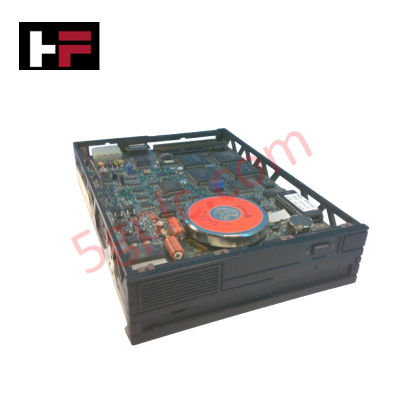
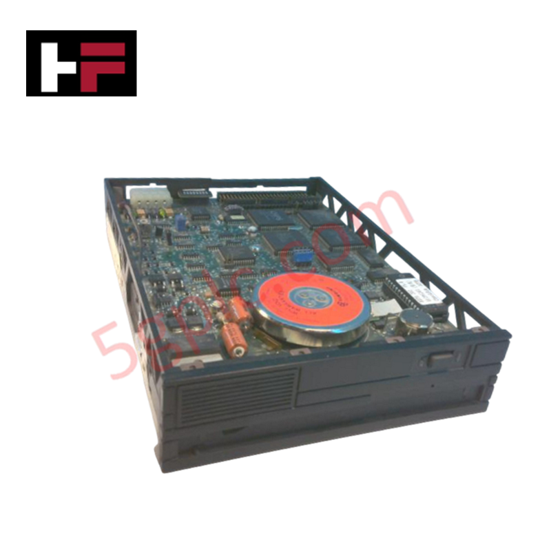
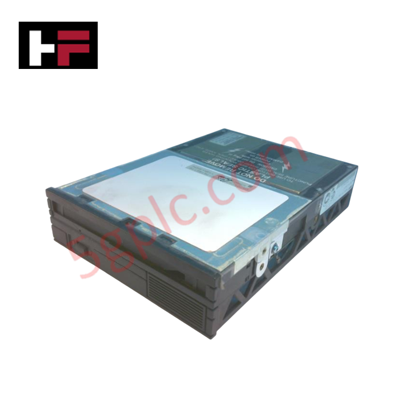
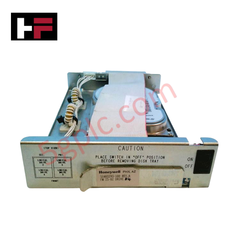
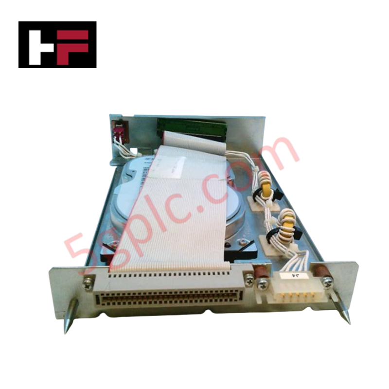
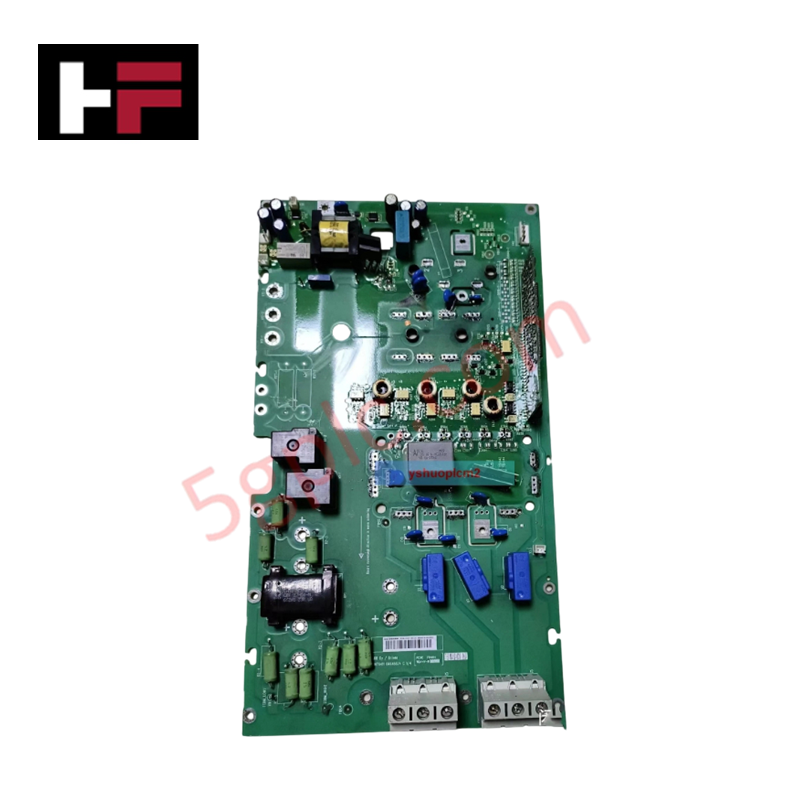
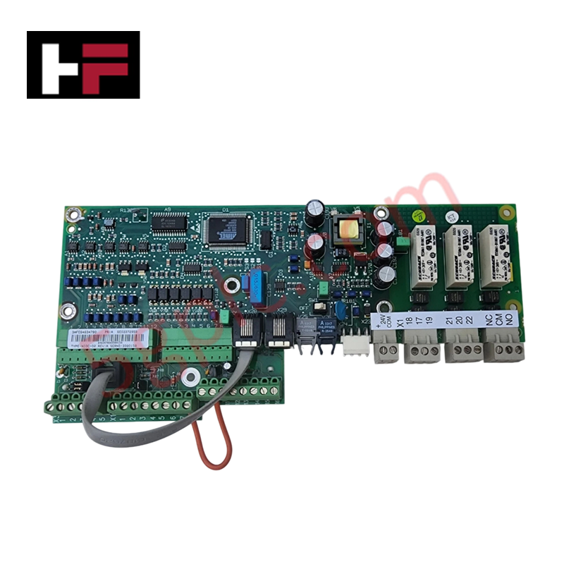
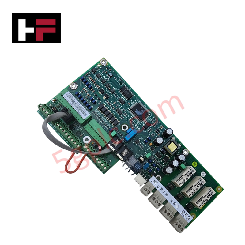
The Honeywell 51195156-300 serves as the primary 51195156-300 Drive Board utilized to execute cartridge drive data storage and physical transport control across legacy control platforms. The electronic assembly monitors rotational parameters, manages hardware indexing loops, and maintains interface synchronization with main processing units under strict electronic timing schedules.
Hardware Specifications
| Parameter | Specification |
|---|---|
| Model | 51195156-300 |
| Brand | Honeywell |
| Series / Module Type | Legacy Control System / Cartridge Drive Board |
| Origin | USA |
| Weight | 1.71 kg (3.77 lbs) |
| Dimensions | Standard multi-layer card rack profile |
| Operating Temp | 0 to +60 deg C (Standard backplane internal ambient) |
| Power Consumption | 5-12 VDC operational range, 2 A current draw limit |
| Storage Capacity Control | 20 MB legacy media drive systems |
| System Interfacing | CRP interface protocol bus topology |
Channel-to-Channel Isolation and Noise Suppression
The multi-layer circuit layout of the 51195156-300 card architecture includes internal inductive isolation planes designed to limit signal noise leakage into adjacent hardware frames. This layout reduces common-mode voltage spikes on the 5-12 VDC internal power line during high-current disk seeking operations. By shielding high-speed clock traces, the drive board isolates parallel databus nodes, preventing the generation of cross-talk that could distort the 4-20 mA HART loop protocol parameters present on neighboring process control I/O terminations within the same marshalling enclosure.
Frequently Asked Questions
Q: Does the 51195156-300 assembly allow live hot-swap replacement within the processor chassis?
A: No. The board lacks specialized pre-charge pins required to isolate bus lines during insertion. Power down the controller frame before extraction to avoid disrupting backplane data framing or damaging edge connectors.
Q: How are power line drops handled across the board when the cartridge drive pulls its maximum 2 A current?
A: The board includes localized high-capacity decoupling capacitors designed to damp current transients on the 5 VDC and 12 VDC power lines, stabilizing voltages during track change sequences.
Field Installation Guidelines
- Card Guide Alignment: Insert the board into the designated chassis slot using the built-in guide rails. Ensure the card edge connectors align properly with the backplane pin matrix before pressing the card home.
- Grounding Trace Check: Verify the frame grounding spring clips on the module faceplate are clean and make direct contact with the bare metal of the sub-rack housing.
- Cable Separation: Route all parallel ribbon cables away from heavy alternating current lines or electric motor circuits to maintain data frame accuracy on the CRP bus.
- Thermal Clearance Limits: Confirm that cabinet ventilation fans operate within parameters. Maintain clear space below the card rack to allow passive convective airflow to cool the components beneath the +60 deg C operational threshold.
Additional Information
- 100% Genuine Parts: All products are original and authentic, ensuring reliable industrial performance.
- 30-Day Refund Guarantee: Return any in-stock item within 30 days in original, unopened packaging for a full refund (excluding shipping and fees).
- 12-Month Warranty: Covers defects in materials or workmanship; excludes misuse, normal wear, or unauthorized modifications.
- Worldwide Shipping: We ship via USPS, UPS, FedEx, and DHL. Delivery times vary by country and may be subject to customs or import fees.
- Support & Contact: Technical and warranty assistance is available anytime. Contact us here: Contact.
- Purchase Guidance: Check product specifications and compatibility carefully before ordering to ensure proper application.

Tech & Buying Guide

Executing a PLC System Site Acceptance Test (SAT): The Definitive Engineering Guide
The transition of a Programmable Logic Controller (PLC) cabinet from a controlled factory floor to a volatile plant environment represents a critical milestone in factory automation. While a Factory Acceptance Test (FAT) validates standalone hardware compliance under ideal conditions, it cannot replicate real-world process dynamics. Therefore, deploying an industrial automation system requires a rigorous Site Acceptance Test (SAT) to verify total loop integrity, field wiring wiring metrics, and process control parameters before final customer handover.

Advanced Integration: Master Protocol for VFD Commissioning and Testing
Deploying variable frequency drives (VFDs) requires precise execution during the initial commissioning phase. Junior automation engineers often find the first power-up sequence intimidating. However, following a rigorous engineering framework ensures equipment safety and system reliability. Proper startup procedures protect both the drive electronics and the connected motor.

Optimizing Factory Automation: The Definitive Guide to VFD Preventive Maintenance
Variable Frequency Drives (VFDs) serve as critical assets in modern industrial automation. These power electronic devices regulate electric motors by adjusting the supplied frequency and voltage. Consequently, industries utilize VFDs to reduce energy consumption and optimize process control. Major manufacturers like Siemens, ABB, and Yaskawa design highly efficient drives. However, sustained efficiency requires a rigorous preventive maintenance program.