


Product Details
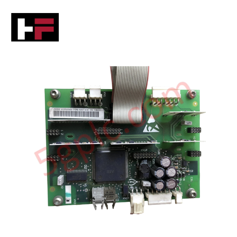
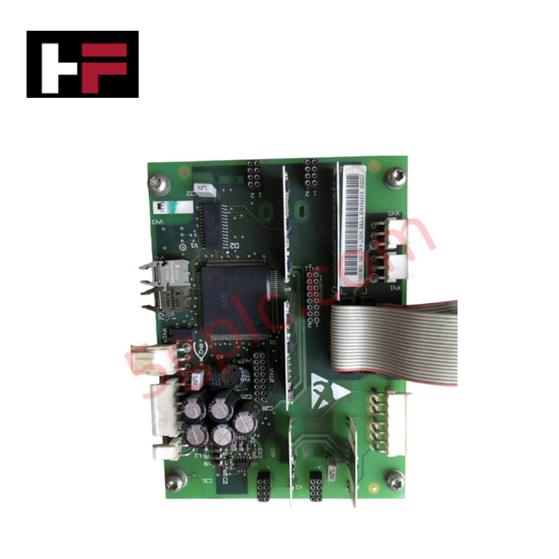
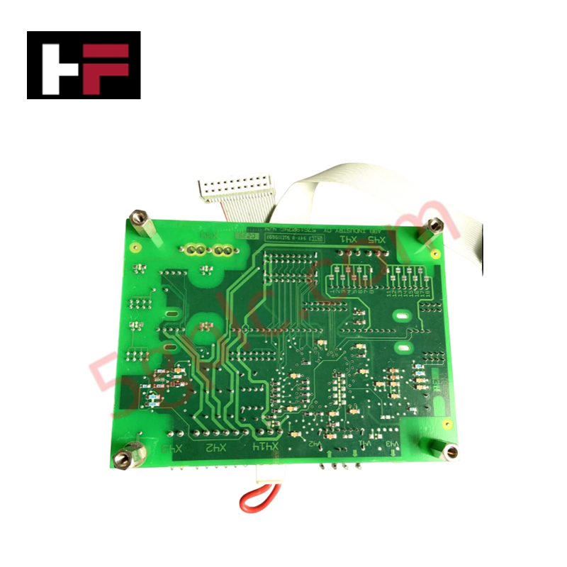
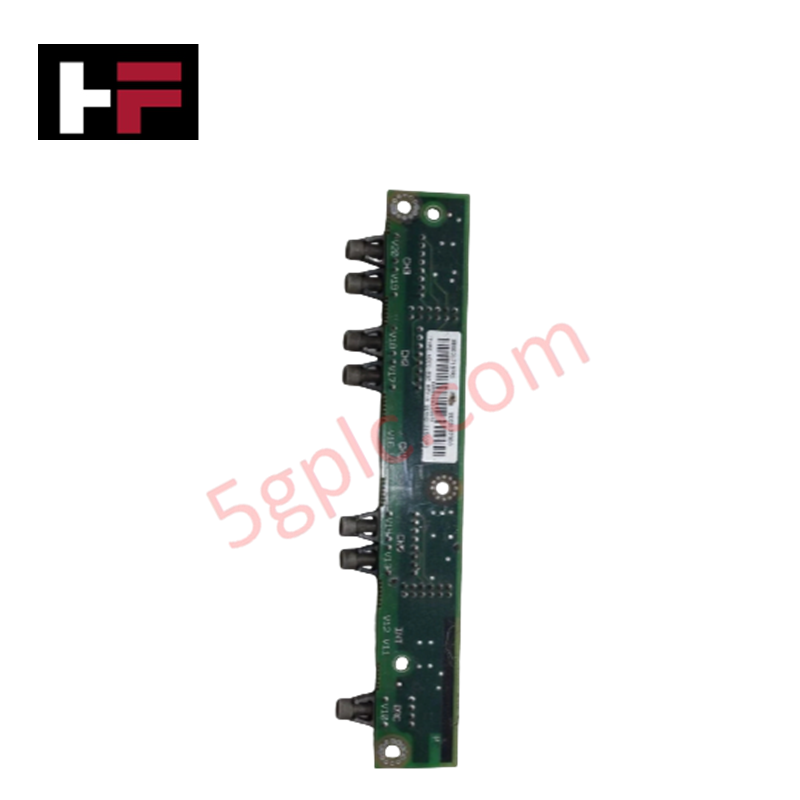
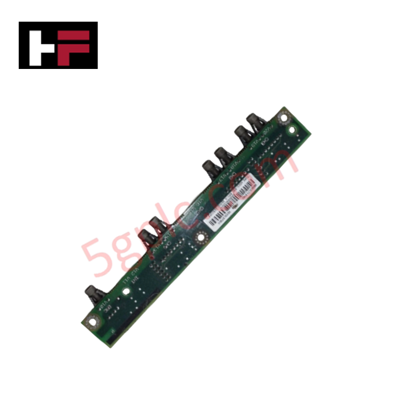
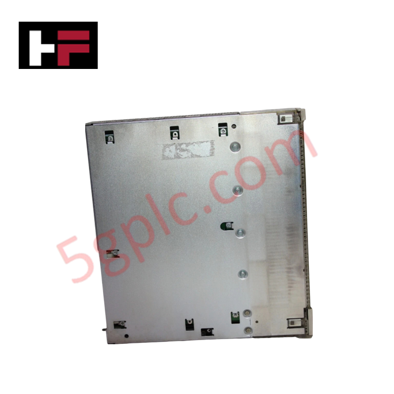
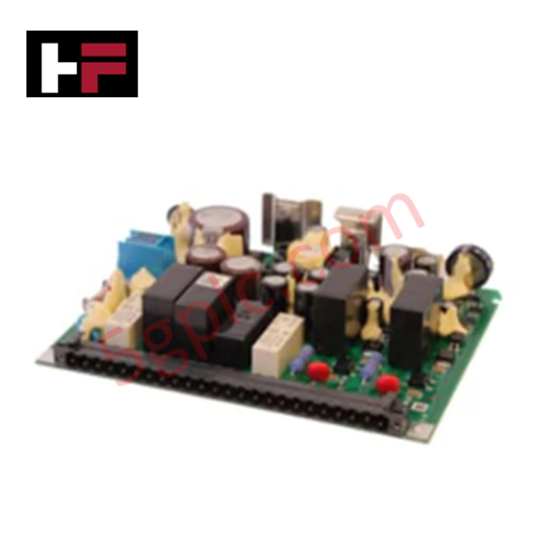
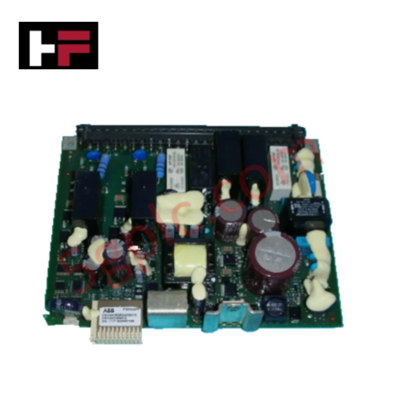
The ABB NINT-63C, also cataloged as the NINT-63C Main Circuit Interface Board, operates as a dedicated hardware component for inverter main circuit signal interfacing within ABB drive control topologies.
Hardware Specifications
| Parameter | Specification |
|---|---|
| Model | NINT-63C (Product ID: 61353330) |
| Brand | ABB |
| Origin | Europe standard sourcing |
| Weight | 0.15 kg |
| Dimensions | Standard internal drive chassis frame allocation |
| Operating Temp | Standard industrial drive cabinet range |
| Power Consumption | Supplied via internal drive gate driver backplane connection |
| Functional Designation | Main Circuit Integration Interface |
| Minimum Order Quantity | 1 piece |
Profinet / EtherNet/IP Deterministic Networks and Firmware Flash Compatibility
The ABB NINT-63C processes local gates, fault metrics, and phase current voltages directly matching the inverter's power switches. It routes critical intermediate-circuit signals through standard backplane traces while ensuring synchronous execution across multi-drive branch systems. When integrated within large automation loops, this circuit hardware isolates local signal paths to sustain low latency requirements of Profinet / EtherNet/IP deterministic networks. The layout layout matches local memory buffers, which protects underlying drive control software allocations and ensures absolute firmware flash compatibility during critical lifecycle field modifications.
Frequently Asked Questions
Q: Can the NINT-63C interface board be uninstalled while the drive system intermediate DC bus is charged?
A: No. The board must never be handled until the main power input is disconnected and the internal DC link capacitors are fully discharged according to the drive specification timing. Residual charge can cause immediate electrical damage to the interface tracks.
Q: How is galvanic isolation verified across the gate driver connections on this board?
A: Isolation paths are physically etched directly into the circuit layout design to separate the high-potential main power circuit components from the low-voltage control backplane electronics, preventing cross-channel electrical damage during voltage fluctuations.
Field Installation Guidelines
- Terminate all input power networks and ensure the main chassis is de-energized prior to fitting the board into the mounting carriage.
- Secure the printed circuit assembly firmly to the metallic frame using all provided screw grounding locations to ensure a reliable path for high-frequency electrical noise.
- Keep control signal wiring separated from three-phase AC power paths within the drive housing to prevent inductive coupling and data corruption.
- Check the fiber-optic or parallel ribbon cable connectors for physical alignment before fully interlocking the main harness socket to avoid bent contact pins.
Additional Information
- 100% Genuine Parts: All products are original and authentic, ensuring reliable industrial performance.
- 30-Day Refund Guarantee: Return any in-stock item within 30 days in original, unopened packaging for a full refund (excluding shipping and fees).
- 12-Month Warranty: Covers defects in materials or workmanship; excludes misuse, normal wear, or unauthorized modifications.
- Worldwide Shipping: We ship via USPS, UPS, FedEx, and DHL. Delivery times vary by country and may be subject to customs or import fees.
- Support & Contact: Technical and warranty assistance is available anytime. Contact us here: Contact.
- Purchase Guidance: Check product specifications and compatibility carefully before ordering to ensure proper application.
Tech & Buying Guide

Industrial PC vs. Commercial PC: Selecting the Right Hardware for Automation
In the demanding world of factory automation, selecting the correct computing platform is critical for system reliability. While commercial PCs power our daily lives, they often fail when subjected to the harsh realities of the production floor. Understanding the fundamental differences between an Industrial PC (IPC) and a standard office PC helps engineers optimize control systems for longevity and performance.

Core Components of Programmable Logic Controllers (PLC) in Industrial Automation
A Programmable Logic Controller (PLC) serves as the digital backbone of modern factory automation. Whether you are managing complex assembly lines or simple process loops, understanding the hardware and software architecture of a PLC is essential for any control systems engineer.

PLC vs. PC: Navigating the Architectural Differences in Industrial Automation
In the realm of factory automation, professionals often debate the roles of Programmable Logic Controllers (PLCs) and Personal Computers (PCs). While both devices share fundamental computing architectures—including a processor, memory, and an operating system—their design philosophies diverge significantly. Understanding these distinctions is critical for selecting the right hardware for your industrial control systems.